Silencer
24 Dry Exhaust System
17
Silencer
a) An engine correctly installed in accordance with this
handbook will meet the emission requirements of the
RCD (see back of manual).
b) Keep exhaust systems to a minimum length and
have gradual bends (NOT right angle elbows).
Exhaust back pressure is increased by longer exhaust
length and sharp bends. Back pressure should be
measured; with the complete exhaust system
connected and the engine running at full speed; and
should NOT exceed 80mm Hg (3.1 inches Hg). The
correct measuring point is before the dry exhaust
bellows (at the manifold flange). We can supply a
Manometer kit for testing ‘Back Pressure’.
c) The dry exhaust system installed in a canal boat
or work boat should be 1
1
/
2
” minimum internal
diameter.
The engine is fitted with a 1
1
/
2
” BSP male connector
stub as standard - Valid for exhaust systems up to 3
metres in length. A flexible exhaust bellows and dry
exhaust silencer should be used. It is up to the
installer to work out his own pipe run but care
should be taken as follows:
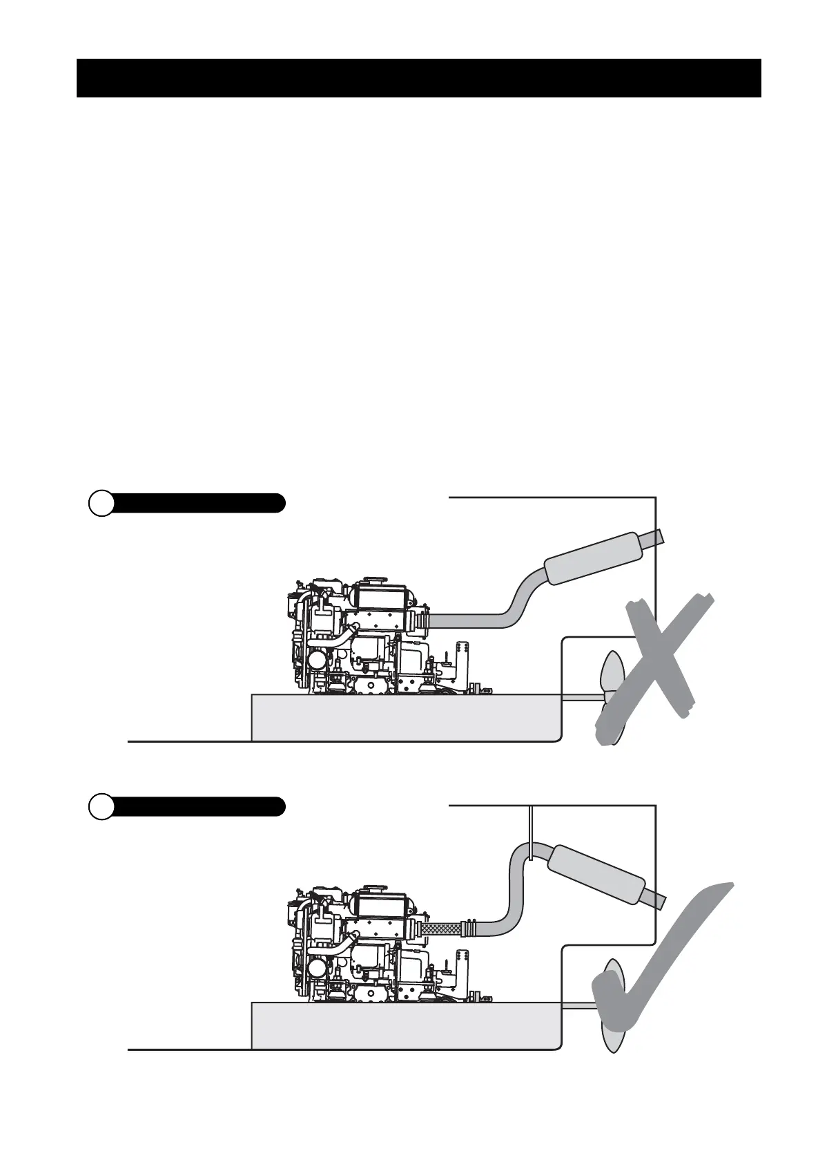
• Never use a flexible exhaust bellow as a bend, it will
crack, always keep them straight.
• Ensure that rain water cannot enter the exhaust port
and run back down the system, flooding the silencer
and eventually the engine. (See drawings below).
• The system should be lagged if there is any danger of
the crew getting near it.
• A dry exhaust system will give off considerable heat
and suitable ventilation must be provided.
DRY EXHAUST INSTALLATION
23 Dry Exhaust System
Ensure exhaust raises then falls to outlet
1640_Aug_2013.qxd:beta 1660 manual 18/11/13 10:48 Page 17



 To Next Page