Betts Industries Inc. ▪ 814·723·1250 ▪ 1800 Pennsylvania Ave. West ▪ Warren, PA 16365 ▪ www.BettsInd.com
Print Date: 11/21/2023 This form is considered uncontrolled 24 hrs. after print date.
6.1 Disassembly
6.1.1 Use the two ½” open ended wrenches to remove the Control Knob (8) and the
Flange Nut (7) from the piston (2). If the flange nut (7) is spinning with the piston, use
a small screwdriver to pop off the end cap (10). Insert a 7/32” Allen wrench into the
end of the piston to prevent it from spinning to remove the Flange Nut (7).
6.1.2 Push the piston (2) through the back of the valve. If the end cap (10) is still on, apply
enough force to pop the end cap and piston out through the back of the valve.
6.1.3 Remove the O-rings (3) from the piston. Using your fingers, squeeze the O-rings (3)
up to be able to slide a plastic O-ring pick under the O-ring and pull it off the piston.
Do not use a sharp pick which may scratch or damage the O-ring grooves on the
piston. The polyurethane detent O-ring (4) is a split O-ring and can easily be pulled
off the piston. Discard the used O-rings.
6.1.4 Clean and inspect the piston (2). Replace if there is any wear or damage.
6.1.5 Clean and inspect the control block (1) bore. Replace if there is any wear, corrosion,
or damage.
6.1.6 Inspect the bushing (5) for corrosion or damage. If it needs replaced, use the .495
diameter pin and push out the bushing (5) using an arbor press.
6.2 Rebuild
6.2.1 If the Bushing (5) was removed, it must be pressed into the Control Block (1) using
an arbor press. Retaining compound is recommended but do not get compound in
the bore of the bushing (5) and clean off all excess compound after assembly.
Ensure that the bushing (5) starts straight and presses flush with the thread face of
the control block (1).
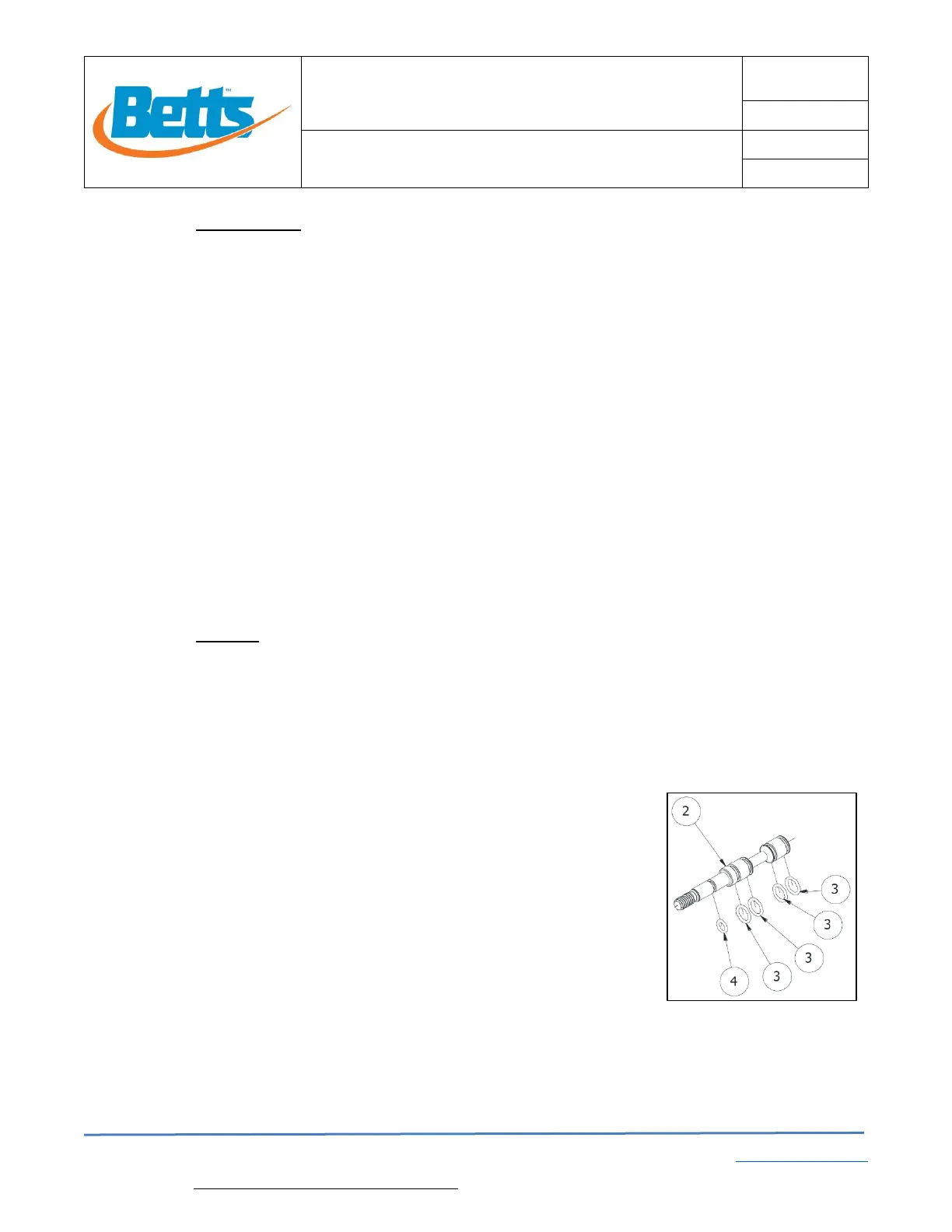
6.2.2 The Detent O-ring (4) is a white polyurethane O-ring. Use a razor blade and cut the
O-ring in one spot. The cut location is not critical.
6.2.3 Install the split Detent O-ring (4) onto the Piston (2) in
the location as shown in Fig. 3.
6.2.4 Install the other O-rings (4) onto the Piston (2) in the
locations as shown in Fig. 3.
6.2.5 Lubricate all O-rings (3) using low temperature silicone
lubricant. Ensure that O-rings are compatible with any
airline conditioner/antifreeze.
6.2.6 Insert the piston (2) with all O-rings into the Control
Block (1). Be careful when inserting the piston to
prevent any O-ring damage.
6.2.7 If attaching to a panel, insert the Control Block into the panel and thread on the panel
Jam Nut (6). Apply thread lock compound to the threads to prevent vibration from
loosening the nut.
6.2.8 Apply thread lock compound to the piston threads and thread on the Flange nut (7)
until it bottoms out on the piston (2). Thread the control knob (8) down to the flange
 Loading...