INSTALLATION MANUAL
ENGLISH
1) GENERAL INFORMATION
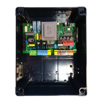
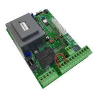
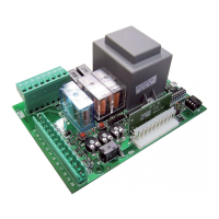
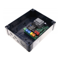
The ALENA SW2 CPEM control panel comes with standard factory settings. Any
change must be set by means of the TRIMMER and DIP SWITCH settings.
Its main features are:
- Control of 1 or 2 motors single-phase
Note: 2 motors of the same type must be used.
- Electronic torque control
- Slowdown while opening and closing
- Separate inputs for safety devices
- Built-in radio receiver rolling code with transmitter cloning.
The board has a terminal strip of the removable kind to make maintenance
or replacement easier. It comes with a series of prewired jumpers to make the
installer’s job on site easier.
The jumpers concern terminals: 70-71, 70-72, 70-74, 41-42, 41-43, 41-44,
41-45. If the above-mentioned terminals are being used, remove the rel-
evant jumpers.
TESTING
TheALENA SW2 CPEM panel controls (checks) the start relays and safety devices
(photocells) before performing each opening and closing cycle.
If there is a malfunction, make sure that the connected devices are working
properly and check the wiring.
2) TECHNICAL SPECIFICATIONS
Power supply *
110-120V 60Hz
220-230V 50/60 Hz
Low voltage/mains insulation > 2MOhm 500V
Operating temperature range -20 / +55°C
Dielectric rigidity mains/LV 3750V~ for 1 minute
Maximum motor power 400W+400W
Accessories power supply 24V ~ (demand max. 0,2A)
Solenoid lock see Fig. F1-F2
AUX 0 - Flashing
Contact powered
120V~ 40W max
230V~ 40W max
Fuses see Fig. B
Built-in Rolling-Code
radio-receiver
frequency 433.92MHz
Setting of parameters and logics TRIMMER + DIP SWITCH
N° of combinations 4 billion
Max.n° of transmitters that can be memorized 63
Pedestrian work time 8 s.
Maximum work time
120s
Usable transmitter versions:
All ROLLING CODE transmitters compatible with
Terminal Denition Description
Power
supply
L LINE
Single-phase power supply with earth cable
N NEUTRAL
GND EARTH
Motor
10 START + CONDENSER
Motor and condenser connection. Time lag during closing. (Can be adjusted with trimmer T4)
11 COM
12 START + CONDENSER
14 START + CONDENSER
Motor and condenser connection. Time lag during opening. 2s
Note: if T4=0, do not connect any cable to terminals 14-15-16
15 COM
16 START + CONDENSER
Aux
20
AUX 0 – 230V POWERED CONTACT
(N.O.) (40W MAX)
Exit due to FLASHING LIGHT.
Contact stays closed while leaves are operating.
21
28
Solenoid lock
see Fig. F1-F2
29
Limit switches
40 Not used
41 +REF SWE Limit switch common
42 SWC1 Motor 1 closing limit switch SWC1 (N.C.).
43 SWO1 Motor 1 opening limit switch SWO1 (N.C.).
44 SWC2 Motor 2 closing limit switch SWC2 (N.C.).
45 SWO2 Motor 2 opening limit switch SWO2 (N.C.).
Accessories
power
supply
50
0V
~
Accessories power supply output.
51
24V
~
52
24 Vsafe
~
Tested safety device power supply output (photocell transmitter and safety edge transmitter).
Output active only during operating cycle.
Commands
60 Common START and OPEN inputs common
61 START
START command button (N.O.).
Operation according to “3/4-STEP” logic
62 OPEN
OPEN command button (N.O.).
Gate opened with this command. If the input stays closed, the leaves stay open until the contact is opened.
When the contact is open, the automated device closes following the TCA time, where activated.
Safety devices
70 Common STOP, PHOT and BAR inputs common
71 STOP
The command stops movement. (N.C.)
If not used, leave jumper inserted.
72 PHOT (*)
PHOTOCELL input (N.C.).
Operation according to “PHOTOCELL/PHOTOCELL DURING CLOSING” logic. If not used, leave jumper inserted.
73 FAULT 1 Test input for safety devices connected to PHOT.
74
BAR /
BAR CL /
BAR TEST /
BAR CL TEST /
BAR 8K2 /
BAR CL 8K2
(*)
Safety edge input (N.C.).
If not used, leave jumper inserted
BAR/8K2
dip
Safety
edge
check dip
Safety edge
operation
dip
OFF OFF OFF NC input, no verication, reversal while opening and closing (BAR)
OFF OFF ON NC input, no verication, reversal only when closing, stop when
opening (BAR CL)
OFF ON OFF NC input, with verication, reversal while opening and closing (BAR
TEST)
OFF ON ON NC input, with verication, reversal only when closing, stop when
opening (BAR CL TEST)
ON OFF OFF 8K2 input, reversal when opening and closing (BAR 8K2)
ON OFF ON 8K2 input, reversal only when closing, stop when opening (BAR CL 8K2)
ON ON OFF ---
ON ON ON ---
75 FAULT 2 Test input for safety devices connected to BAR.
Antenna
Y ANTENNA
Antenna input.
Use an antenna tuned to 433MHz. Use RG58 coax cable to connect the Antenna and Receiver. Metal bodies
close to the antenna can interfere with radio reception. If the transmitter’s range is limited, move the antenna
to a more suitable position.
# SHIELD
(*) If “D” type devices are installed (as dened by EN12453), connect in unveried mode, foresee mandatory maintenance at least every six months.
(*) In the European Union, apply standard EN 12453 for force limitations, and standard EN 12445 for measuring method.
ALENA SW2 CPEM - 23
D812801 00100_01

 Loading...