INSTALLATION MANUAL
2) GENERAL INFORMATION
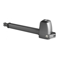
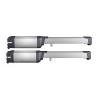
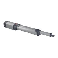
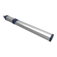
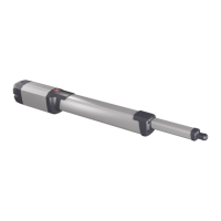
Electromechanical operator designed to automate residential-type gates.
The gearmotor keeps the gate locked on closing and on opening, without
needing an electric lock for leaves up to 2 m long. For leaves ranging
between 3m and 5m long, the electric lock becomes indispensable.
The operator is provided with an electronic torque limiter. It must be
controlled by an electronic control panel provided with torque setting.
The operator is provided with an obstacle detection system complying
with EN12453 and EN 12445 standards.
3) TECHNICAL SPECIFICATIONS
Power supply*
single phase 220-230V~ ±10% 50/60 Hz **
Absorbed power 200 W
Absorbed current 0,9 A
Insulation class F
Thermal protection 140 °C (self-resetting)
Pushing and towing force 3000 N (~300 kg)
Speed 18 mm/s
Manual manoeuvre Triangular key
Environmental conditions from -20 °C to + 55 °C
Type of use semi-intensive
Operation cycle
230V: 14 cycles/h (20°C)- 6 cycles/h (55°C)
120V: 9 cycles/h (20°C)- 4 cycles/h (55°C)
Maximum leaf length with-
out electric lock
2 m
Maximum leaf length with
electric lock
ATHOS AC 25A ATHOS AC 40A
2,5 m 3500N (~350 kg)
without slowdowns
4 m 2000N (~200 kg)
without slowdowns
2,5 m 7000N (~700 kg)
with slowdowns
4 m 4000N (~400 kg)
with slowdowns
3 m 2400N (~240 kg)
without slowdowns
Degree of protection IP 54
Operator weight 53N (~5,3kg)
Lubrication
permanent grease
Sound pressure <70dB(A)
Condenser
120V: 30 uF
230V: 8 uF
(*other voltages to order)
**In the event of a power supply at 60Hz, the maximum weight of leaf dedu-
ced from the diagram “Length” vs “Weight” is to be reduced by multiplying
it by the coecient k = 0.7
Pmax 60Hz = Pmax 50Hz x 0.7
4) TUBE ARRANGEMENT Fig. A
Install the electrical system referring to the standards in force for electrical
systems CEI 64-8, IEC 364, harmonization document HD 384 and other
national standards.
Warning! For actuator wiring and accessory connection, refer to the
relevant instruction manuals. The control panels and accessories must
be suitable for use and conform to current standards.
Should the opening or closing direction be incorrect, it is possible to invert
the connections of operation 1 and operation 2 on the control board.
The rst command after an interruption of the power supply should be
an opening manoeuvre.
5) INSTALLATION DIAGRAM Fig. B
P rear bracket fastening to pillar
F front fork fastening leaf
a-b distances for determining bracket “P” fastening point
C value of fastening centre-to-centre distance
D gate length
X distance from gate axis to corner of pillar
S half door thickness
Z value always greater than 45 mm (b - X)
kg max. weight of leaf
α° leaf opening angle
6) PILLAR FASTENINGS INSTALLATION DISTANCES Fig. B
6.1) How to read the installation distance tables
Select “a” and “b” according to the angle in degrees α° that the gate has
to open.
If there is too large a dierence between “a” and “b”, the leaf will not travel
smoothly and the pushing or pulling force will uctuate during its stroke.
To respect the opening speed and ensure the controller operates correctly,
it is best to keep the dierence between “a” and “b” as low as possible.
The table has been worked out for A40 mm thick medium-size gate.
Always check that there is no possible collision between the gate and
the operator.
7) FASTENING OF FITTINGS TO PILLAR Fig. C
8) MOTOR CORRECT ASSEMBLY Fig. D
NOTES The motor must be assembled correctly as in gure D.
The operator’s incorrect assembly causes the actuator and performance
in general to fail the IP rating.
9) CORRECT HEIGHT FROM GROUND TO COMPLY WITH Fig. E
10) ATTACHING MOTOR TO FASTENING ON PILLAR Fig. F
NOTES: the nut must not be xed inside the hexagonal seat but only until
it touches the half-body. The nut must not put pressure on the half-body.
11) MAXIMUM TILT Fig. G
12) CORRECT INSTALLATION Fig. H
Correct installation entails maintaining a rod stroke margin of approx.
5-10 mm to avoid possible trouble with operation.
13) FASTENING OF FITTINGS TO LEAF Fig. I
IMPORTANT: THE FRONT BRACKET MUST BE FITTED WITH THE SLOTS
FACING DOWN (AS IN THE FIGURE)
Align the front and back brackets as in Fig. I.
14) OPERATOR ATTACHMENT ON DOOR Fig. J
NOTES: the nut must not be xed inside the hexagonal seat but only
until it touches the joint attachment. The nut must not put pressure on
the joint attachment.
15) DIMENSIONS Fig. K
16) TIPS FOR SPECIAL INSTALLATIONS Fig. L.
With the leaf fully open, create a recess to accommodate the operator.
With the leaf fully open, create a recess to accommodate the operator.
Fig. L shows the minimum recess dimensions.
If distance “b” is greater than the values given in the installation tables:
- create a recess in the pillar Fig. M
- move the leaf so that it is ush with the pillar Fig.N.
17) LEAF STOPS AT GROUND LEVEL Fig. O
For the actuator to work properly, it is advisable to use stops “Fig. O Rif. 1”
to stop the leaves both when they are open and closed, as illustrated in g.
The leaf stops must prevent the actuator rod from reaching the end of
its travel.
18) MANUAL OPENING (See USER GUIDE -FIG.Y,Y1-).
19) ELECTRIC LOCK (Fig. Y)
WARNING: In the case of leaves longer than 2m, it is indispen-
sable to install a solenoid latch.
For electric lock connection, the optional board is required (refer
to the appropriate instruction).
0
1,5 2 2,5 3
100
200
300
400
500
600
700
800
900
1000
1100
1200
1300
1400
1500
1600
1700
1800
1900
2000
2100
T3=0
T3>0
m
kg
ATHOS AC 25A
0
2 2,5 3 4
100
200
300
400
500
600
700
800
900
1000
1100
1200
1300
1400
1500
1600
1700
1800
1900
2000
2100
3,51,5
m
kg
T3>0
T3=0
ATHOS AC 40A
22 - ATHOS AC 25A-ATHOS AC 40A
D812957 00500_04
 Loading...