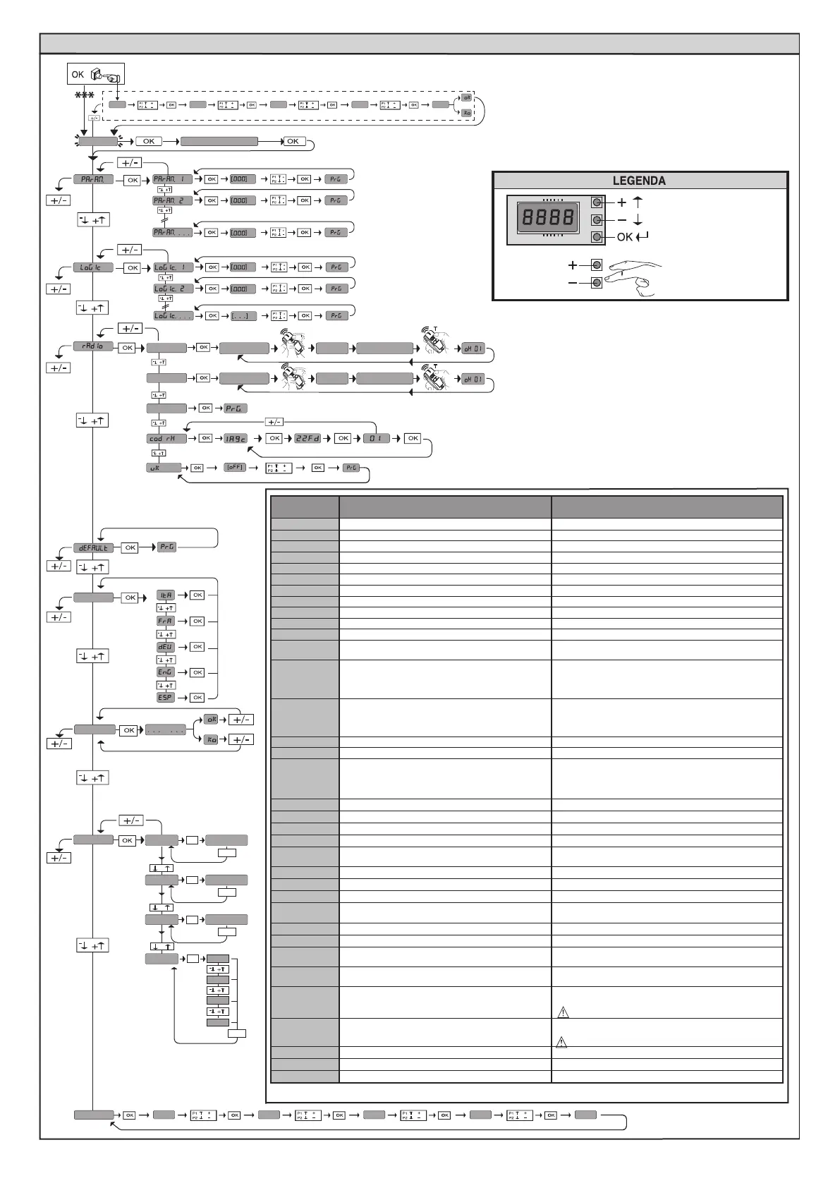
ACCESS MENUS Fig. 2
Exit Menù
Conrm/Switch on display
Scroll up
Scroll down
autoset
See PARAMETERS MENU
See LOGIC MENU
See RADIO MENU
add. start
hidden butt
hidden butt
release
release
desired button
desired button
Add. 2ch
erase 64
language
stat
-
+
-
+
OK
vers
bft . . .
+/-
OK
0000
+/-
+/-
n. cycles
OK
OK
password
0---
10--
150- 1520 prg
00
-
+
err
+/-
n. remotes
List of last 30 errors
Control unit
software version
No total
manoeuvres(in hundreds)
No radio control
devices memorised
ALT follow the user guide
x2
0---
10--
150- 1520 ok
01.33
02.01
........
30.15
*** Password entry.
Request with Protection Level logic set to 1, 2, 3, 4
Diagnostics
code
DESCRIPTION NOTES
STRE
START E external start input activated
STRI
START I internal start input activated
OPEN
OPEN input activated
CLS
CLOSE input activated
PED
PED pedestrian input activated
TIME
TIMER input activated
STOP
STOP input activated
PHOT
PHOT photocell input activated
PHOP
PHOT OP opening photocell input activated
PHCL
PHOT CL closing photocell input activated
BAR
BAR safety edge input activated
BAR 2
BAR safety edge input activated on slave motor
(opposite leaves connection)
baro
Activation of BAR safety edge input with ACTIVE reversal
ONLY WHILE OPENING, or, if congured as veried safety
edge active only while opening, Activation of the asso-
ciated FAULT input
barc
Activation of BAR safety edge input with ACTIVE rever-
sal ONLY WHILE CLOSING, or, if congured as veried
safety edge active only while closing, Activation of the
associated FAULT input
SWC
SWC motor closing limit switch input activated
SWO
SWO motor opening limit switch input activated
SET
The board is standing by to perform a complete opening-
closing cycle uninterrupted by intermediate stops in
order to acquire the torque required for movement.
WARNING! Obstacle detection not active
ER01
Photocell test failed
Check photocell connection and/or logic settings
ER02
Safety edge test failed
Check safety edge connection and/or logic settings
ER03
Opening photocell test failed Check photocell connection and/or parameter/logic setting
ER04
Closing photocell test failed Check photocell connection and/or parameter/logic setting
ER05
Safety edge test on slave motor failed (opposite leaves
connection)
Check safety edge connection and/or parameter/logic settings
er06
8k2 safety edge test failed Check safety edge connection and/or parameter/logic settings
ER07
Opening safety edge test failed Check safety edge connection and/or parameter/logic settings
ER08
Closing safety edge test failed Check safety edge connection and/or parameter/logic settings
ER1x*
Board hardware test error
- Check connections to motor
- Hardware problems with board (contact technical assistance)
ER3x*
Reverse due to obstacle - Amperostop Check for obstacles in path
ER4x*
Thermal cutout Allow automated device to cool
ER5x*
Communication error with remote devices
Check connection with serial-connected accessory devices
and/or expansion boards
ER70, ER71
ER74, ER75
Internal system supervision control error.
Try switching the board o and back on again. If the problem
persists, contact the technical assistance department.
ER72
Consistency error of the control unit’s parameters (Logics
and Parameters)
Pressing OK the detected settings are conrmed. The board will
keep on working with the detected settings.
The board settings must be checked (Parameters and Logics)
ER73
D-track parameter error
Pressing OK, the board will keep on working with D-track as
a default.
An autoset is required
ERf0
Limit switch error
check limit switch connections
erf1
Limit switch error always active after operation start
Check limit switch and motor connections
ERf3
Error in setting the SAFE inputs Check the setting of the SAFE inputs is correct
* X = 0,1,…,9,A,B,C,D,E,F
24 - ARES ULTRA BT A 1000 - ARES ULTRA BT A 1500
D812201 00100_09
 Loading...