• Fix the two supporting brackets to the ceiling, as in fig.12. Recheck
everything and fix the two supporting brackets to the gearmotor base
plate.
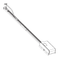
• Release the towing carriage (fig.13) by pulling the wire, and bring the
towing arm as far as the door panel. Fix the towing arm to the door panel,
as in fig.14, using the screws supplied.
5) ELECTRICAL INSTALLATION SET-UP (Fig.15)
I) Type-approved omnipolar circuit breaker with at least 3-mm contact
opening, provided with protection against overloads and short circuits,
suitable for cutting out automation from the mains. Place, if not al ready
installed, a type-approved differential switch with a 0.03 A threshold just
before the automation system.
Qr) Control panel and incorporated receiver
M) Actuator
Ft) Transmitter photocell
Fr) Receiver photocells
T) 1-2-4 channel transmitter.
Connect the accessories, safety and control devices to the motor unit,
making sure that the mains voltage connections are kept totally separate
from the low voltage accessory connections. Proceed as illustrated in the
electrical diagram (fig.15). When this operation is completed, the appliance
is ready to work by means of a remote control.
5.1) Terminal board connections
The automation device is to be operated after all the safety devices have
been connected and checked. See terminal board diagram in fig.16.
JP1
1-2 Motor connection (1 Green - 2 Brown)
3 Transformer connection 0Vac
4 Transformer connection 25Vac
5 Transformer connection 15Vac
JP3A Stop microswitch connector
JP3
11-12 Antenna connection (11 signal, 12 braid)
13-14 Supply to accessories 24Vac
15-16 Free contact (N.O.) to be used as Open Gate Warning light (24Vac
max 3W) or 2nd radio channel This option can be set from menu B,
see paragraph on programming.
JP5
22-23 START button (N.O.)
22-24 STOP button (N.C.). If not used, leave bridged.
22-25 Electric edge photocell PHOT input (N.C.). If not used, leave bridged.
JP6
26-27 Courtesy light connection 230Vac max 25W
28-29 Transformer supply 230Vac
30-31 Single-phase supply 230Vac, 50/60Hz (30N-31L)
32-33 Blinker connection 230Vac max 40W
JP7 Slow-down microswitch connector.
6) MANUAL PROGRAMMING OF CONTROL UNIT
6.1) Tests
In order to facilitate the automation setup tests, to control the opening and
closing manoeuvres, you can use the remote control or temporarily connect
a button between the two terminals 22 and 23 (START).
6.2) Trimmer adjustment (Fig.16)
WARNING! Before any adjustment, close jumper J1.
Set the trimmers to the requested value considering that the set value is
increased by turning the relevant trimmer clockwise.
WARNING! The values set using the trimmers must be stored in the
memory.
This operation can be carried out in 2 different ways:
a) Disconnect and then reconnect the power supply (reset) after any
correction to the trimmer. After completing the adjustment, wait at least
5 seconds from system reset and open the J1 jumper.
b) Enter “menu A” after adjusting the trimmers (press SW1-SW2 one time
simultaneously). Check that Check that the LED flash correspond to that
of the “Menu A” (the Green LED flashes in a constant way). After each
trimmer correction, enter “Menu A” to store the new value.
TCA) Dwell time after which the door is automatically closed. Can be set
from 20 to 120 s.
WARNING: Check that the impact force value measured at the
points established by the EN EN 12445 standard is lower than
that specified in the EN 12453 standard.
AMPC) Sets the amperometric limit switch trigger current during the closing
manoeuvre (antisquash sensitivity). When the limit switch is triggered,
it stops the door and reverses the movement.
AMPO) Sets the amperometric limit switch trigger current during the
opening manoeuvre. When the limit switch is triggered, it stops the door
movement.
WARNING: Excessive value setting can jeopardise antisquash safety.
Setting must be calibrated to the minimum value needed to carry out
complete opening and closing strokes. In any case, the pushing force
at the edge of the door must be within the limits provided for by the
current standards.
TW) Sets the motor operation time, after which the motor stops. The value
set must be slightly greater than the time needed to close the door.
Can be set from 0 to 60s.
6.3) Setting of programmable parameters and functions
To program the required functions, follow the sequence described in the
“PROGRAMMING” pages. These include a “LEGEND” which explains the
types of signal indication provided by the green and red LEDs. For “Menu
B”, the on/off condition is specified in each individual function.
N.B. To enable function setting or modification, you must close
jumper J1 (fig.16).
Programming is divided into three menus:
A) Radio control storage
B) Function logic setting
C) Memory cancellation
To gain access to each individual programming menu, simultaneously
press keys SW1 and SW2 for a short time, as follows: once for menu A,
twice for menu B and three times for menu C.
If you do not carry out any selection within a working time of 60 seconds
after entering the programming mode, you will automatically exit
programming. When setting is completed, set J1 to Off (open the jumper).
To initialise the control unit with the required setting, disconnect the mains
power supply for a few seconds, and then reconnect it.
6.4) Transmitter storage
See the “Menu A” diagram shown on the “PROGRAMMING” page.
6.5) Function logic setting
See the “Menu B” diagram shown on the “PROGRAMMING” page.
The red LED (DL1) condition (on/off) shows the function selected.
The value given within square brackets [ ] is the value predefined by the
manufacturer. Here follows a detailed explanation of “Menu B” programmable
functions:
Opening photocell [ Red LED On ]
Red DL1 on: when obscured, it excludes photocell operation on opening.
Immediately reverses during the closing phase.
Red DL1 off: when obscured, the photocells remain active during both
opening and closing. If the photocell is obscured during closing, it only
reverses the movement after the photocell has been released.
Opening impulse blocking [ Red LED Off ]
Red DL1 on: the start impulse has no effect during the opening phase.
Red DL1 off: accepts start commands during opening.
Automatic closing [ Red LED Off ]
Red DL1 on: activates automatic closing after a dwell time set by trimmer
TCA.
Red DL1 off: excludes automatic closing.
4 or 2 step logic [Red LED Off ]
Red DL1 on: 2 step logic. A start impulse given while the gate is closing,
causes the direction to reverse; during opening, it causes it to stop.
Red DL1 off: 4 step logic. A start impulse given while the gate is moving,
causes it to stop; the subsequent impulse causes the direction to reverse.
N.B.: The start impulse during the opening phase has no effect when the
opening impulse blocking is enabled (DL1 On).
Gate-open or 2nd radio channel warning light [Red LED On]
Red DL1 on: operation as gate-open warning light (see connection fig.16).
This warning light is off when the gate is closed, blinks when it closing and
stays on when the gate is open or being opened.
Red DL1 off: operation as 2nd radio channel (see connection fig.16).
Allows other devices to be controlled through the second radio channel of
the receiver.
Pre-alarm [Red LED Off ]
Red LED on: the blinker comes on 3 seconds before the motor starts.
Red LED off: the blinker comes on at the same time as the motor starts.
6.6) Cancellation storage
See the “Menu C” diagram shown on the “PROGRAMMING” page.
7) UNIPRO UNIVERSAL PROGRAMMER (See fig.26)
The QTelec control unit can be programmed by means of the UNIPRO
programmer in the following modes:
• TRC/MITTO series radio control programming
• Function logic programming (No Trimmer)
 Loading...