• Memory cancellation
• Parameter reading
Leave the J1 jumper open. The UNIPRO connection only allows reading of
those values set using the trimmers. Connect the UNIPRO programmer to
the TRC/MITTO transmitter by means of the UNITRC/UNIMTTO and
UNIFLAT accessories supplied. Connect the UNIPRO programmer to the
QTelec control unit by means of the UNIDA and UNIFLAT accessories
supplied
N.B.: The QTelec control unit cannot supply the UNIPRO programmer.
For the programming procedure, refer to the appropriate UNIPRO
instruction manual.
8) BELT TENSIONING
The automation is supplied already calibrated and duly tested. If the tension
of the belt needs to be adjusted, proceed as indicated in fig.17a until the
distance between the two branches of the belt is between 15 and 20 mm,
as shown in fig. 17b.
WARNING: The anti-tear spring must never be completely compressed.
Scrupulously check that the spring does not become totally
compressed during operation.
9) LIMIT SWITCH ADJUSTMENT
The controller is provided with a limit switch adjustment unit which is
supplied already adjusted for the maximum stroke available.
The limit switch unit has 2 microswitches for each direction: the first to be
intercepted activated slow-down operation, the second to be intercepted
stops the controller. WARNING: Before carrying out any adjustment
operation, disconnect the power supply from the system.
Each time the system is disconnected from the power supply, the electronics
is reset. When the system is supplied with power, the first starting command
always activates the opening manoeuvre.
To set the opening and closing microswitches, proceed as follows:
• If the towing carriage is in the manual release position, bring it over to
the chain coupling by manually moving the door until it is hooked, and
supply the system with power.
• Press START: the first command always activated the opening
manoeuvre. Press START to stop the door when it is fully open. To set
the stroke limit, lift the retaining spring away from the cam teeth by
means of a screwdriver (fig.18), turn the opening cam in the direction of
the “OPEN” microswitches until you hear the first and second limit
switches click. Lower the spring until one of the cam teeth is engaged.
• Supply the system with power and press START to activate the closing
manoeuvre. Press START when the door is fully closed. Lift the retaining
spring away from the cam teeth by means of a screwdriver (fig.18), turn
the closing cam in the direction of the “CLOSE” microswitches until you
hear both the limit switches click. Lower the spring until one of the cam
teeth is engaged.
• Supply the system with power and check that the door slows down and
stops in both directions. Check that the opening and closing stop actions
do not require excessive towing or compression force.
• Repeat the complete opening and closing manoeuvres a few times to
check that the limit microswitches operate correctly. If necessary,
readjust the cam position.
• The retaining spring must always be engaged in the cam toothing to
keep the cams into position.
• Refit the cover on the controller.
10) SLOW-DOWN SPEED AND TORQUE
N.B.: In the case where, during the final opening and closing phases, the
pushing force does not allow the required manoeuvre to be completed, the
gearmotor force can be increased by moving the transformer connection
from terminal 3 to terminal 4, as in fig.20.
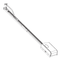
11) EMERGENCY MANOEUVRE
In case of electric power failure or system malfunction, the manoeuvre must
be carried out manually by pulling the wire connected to the carriage, as in
fig.21. For garages which are not provided with a second exit, it is
compulsory to fit an external key release device like Mod. SM1 (fig.22) or
Mod. SET/S (fig.23).
12) AUTOMATION CHECK
Before the automation device finally becomes operational, scrupulously
check the following conditions:
• Check that all the safety devices (limit microswitches, photocells,
electric edges etc) operate correctly.
• Check that the pushing force (antisquash) of the door is within the limits
provided for by the current standards.
• Check that the chain-tightener spring is not completely compressed
during manoeuvre.
• Check the manual opening control operation.
• Check the opening and closing operations using the control
devices fitted.
• Check the normal and customised operation electronic logics.
13) AUTOMATION DEVICE USE
Since the automation device can be remotely controlled by means of a radio
control device or a Start button, and therefore when not in sight, all the
safety devices must be frequently checked in order to ensure their perfect
efficiency. In the event of any malfunction, request immediate assistance
from qualified personnel. Children must be kept at a safe distance from the
automation operation area.
14) AUTOMATION CONTROL
The use of this control device allows the gate to be opened and closed
automatically. There are different types of controls (manual, radio control,
magnetic card access etc.) depending on the installation requirements and
characteristics. For the various control systems, see the relevant instructions.
The automation device users must be instructed on control and operation.
15) MAINTENANCE
Before carrying out any maintenance operation, disconnect the system
power supply.
• Periodically check the tension of the belt (twice a year).
• Occasionally clean the photocell optical elements, if installed.
• Have a qualified technician (installer) check the correct setting of the
electronic clutch.
• When any operational malfunction if found, and not resolved,
disconnect the system power supply and request the assistance of a
qualified technician (installer). When the product is out of service,
activate the manual release device to allow the door to be opened
and closed manually.
16) ACCESSORIES
SM1 External release device to be applied to the cremone bolt already fitted
to the overhead door (fig.22).
SET/S External release device with retracting handle for sectional doors
measuring max 50mm (fig.23).
APT Extension and bracket accessories used to fit the product away from
the door or close to the ceiling (fig.24).
ST Automatic bolt release device for spring-operated overhead doors.
Fitted to the control arm, it automatically releases the side door
bolts (fig.25).
17) SCRAPPING
Warning! This operation should only be carried out by qualified personnel.
Materials must be disposed of in conformity with the current regulations.
In case of scrapping, the automation devices do not entail any particular
risks or danger. In case of materials to be recycled, these should be sorted
out by type (electrical components, copper, aluminium, plastic etc.).
18) DISMANTLING
Warning! This operation should only be carried out by qualified personnel.
When the automation system is disassembled to be reassembled on
another site, proceed as follows:
• Disconnect the power supply and the entire external electrical installation.
• In the case where some of the components cannot be removed or are
damaged, they must be replaced.
The descriptions and illustrations contained in the present manual
are not binding. The Company reserves the right to make any alterations
deemed appropriate for the technical, manufacturing and commercial
improvement of the product, while leaving the essential product
features unchanged, at any time and without undertaking to update
the present publication.
 Loading...