12 SUB-UL
D811290_04
four corners of the actuator centring base. The minimum dimension
between the pillar and rotation shaft axis is shown in g.6.
- Assemble the foundation case by xing its two half sections together
by means of the screws supplied (g.8), and xing small plate “PI” to
the back. Position the box around the actuator, so that small plate
“PI” (g. 8) ts around the shaft, and the edge of the box protrudes
above the ground by about 0.39 in (10mm) (g.6). Position cover “CE”
(g.3) on the box and x its corners with 2 screws.
- Fill the rest of the hole with concrete.
6.5)Cementationofthefoundationcase(toonesideofthehinge-pivot)
Installation with slide arm (to one side of the hinge pivot). This is advisable
when you want to avoid disassembling the existing gate leaf. Area “A”
highlighted in g.9 corresponds to a right-angled triangle having a side
of approximately 7.87 in (200mm), where the actuator axis can be laid
in order to allow the leaf to open by at least 90°.
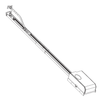
- The drive arm provides a distance between centres between grooved
bush “B” and sliding roller “R” of up to 14.96 in (380mm).
- Bush “B” must be welded to the drive arm with the leaf completely
closed, the roller must be inserted into slide “S” taking into account
the safety degrees shown on small card “CA” (g.11). For slowed-down
versions, also take into account the slow-down degrees (g.13).
- Slide “S” (g.9) can be welded or xed with screws both underneath
and to the side of the leaf. The position of the slide is to be identied
by marking on the leaf the spots reached by sliding roller “R” both
during closing and opening, Having identied the mid-point between
the two markings made previously, align the mid-point of slide “S” and
x it tightly. If slide “S” is shorter than the distance between the two
markings on the leaf, this type of installation is not possible. Keep in
mind that, the nearer slide “S” is to the leaf rotation pivot, the greater
will the leaf speed be. Having identied the actuator position, proceed
to cementing the foundation case as described in paragraph 6.4.
7) BEARING FOUNDATION CASE
Two bearing foundation case models - CPS for SUB and CPS G for SUB
G (g.10) - are available. Having installed the bearing case, the gate
becomes operational even without mounting the actuator, which can
be inserted later. In case of any maintenance needed, this type of case
allows the actuator to be removed without disassembling the gate leaf.
Should the CPS mod. bearing foundation case be used, refer to the
respective manual for the positioning procedure.
8) LEAF MOUNTING
With the actuator in its nal position, proceed as follows.
- Prepare a U-shaped shoe (g.3) where the leaf is to be inserted and
then fastened in its correct position by welding small plate “PS” to it.
- Position grooved bush “B” in the actuator shaft.
- Temporarily fasten the shoe to the leaf: mount the leaf in its completely
closed position, placed over the actuator shaft and perfectly aligned
to the rotation axis.
- Before welding bush “B” to the U-shaped shoe, the right xing point
must be found. To determine the correct point, proceed as described
below.
WARNING: Do not weld bush “B” directly to the leaf. Do not weld the
grooved bush to the actuator output shaft.
8.1) Version without slow-down function
- Release the jack with key “CS” supplied, in the way shown in g.18.
- With the help of pliers, completely rotate the output shaft in the
direction of gate closing along its entire stroke.
- Arrange small card “CA” (g.11) by positioning point “M” in correspon-
dence with the arrow in the casting.
- Rotate the shaft and bring point “G” (right-r.h. or left-l.h.) in corre-
spondence with the arrow.
- Protect the actuator from any metal spots during the subsequent
welding phase.
- The bush can now be welded to the shoe with the leaf mounted in
the gate closed and stopped position. Disassemble the shoe to weld
bush “B” all the way around its circumference.
- Any small defects in levelling foundation plate “P” can be corrected
by means of adjustment dowels “GR” (g.3).
- Place the gate stop on opening in the required position; however, the
gate stop must maintain an extra rotation of at least 5° for safety, in
order to prevent the rack from reaching its end of travel.
NOTE: The rotation degrees of the SUB R versions are highlighted in g.
12; in the case of versions without slow-down function, consider the
slow-down angles (25°+25°) as normal speed. For the SUB G versions,
take into account a total rotation of 185°. For eective 180° openings,
the safety margin is 2.5° both on closing and on opening.
8.2) Version with slow-down function
The versions provided with slow-down function need particular attention
in identifying the xing point of grooved bush “B” (g.3). It is advisable to
use the actuator in a symmetrical way; g.12 shows the 130 degrees of
total rotation of an ordinary actuator, divided into the various phases. By
way of example, g.13 shows the correct operation method for an actuator
carrying out a leaf opening manoeuvre of 90°, that is 20°+ 20° for safety,
70° for normal stroke and 10°+ 10° for slow-down. In order to obtain the
angles described, use small card “CA” on the “SUB R mod.” side (g.11).
WARNING: For eective opening manoeuvres of less than 90°, slow-down
cannot be obtained in both directions. You need to decide beforehand
whether to have slow-down on closing or opening, taking into account
that slow-down begins to happen in the last 25°- 30° of shaft rotation, both
on opening and closing (g.14). Having determined the correct angle for
xing the grooved bush, x it in the way described in paragraphs 8 - 8.1.
NOTE: For the SUB GR versions, take into account a total rotation of
185°, out of which: 2.5°+ 2.5° for safety, 25°+ 25° for slow-down and 125°
for stroke at normal speed. This provides a maximum rotation of 180°.
8.3) Slow-down adjustment (R versions only)
Slow-down adjustment screws “VR” are highlighted in g.15, and can
be adjusted by means of a 3-mm Allen wrench. This must be turned
clockwise to make the movement slower and anticlockwise to make is
less slow. Adjust the slow-down speed so as to prevent the leaf from
slamming when it stops.
8.4)Installationwithslidearm(toonesideofthehinge-pivot)
This type of installation is illustrated in g.9. The installation method is
described in paragraph 6.5. Furthermore, the actuator support base
must be tightly secured to the foundation base by means of screws,
and not just fastened by the four angle bars as in the case of installation
under the hinge-pivot.
9) STOP PLATES
The use of ground stop plates “F” (g.20) is compulsory both on opening
and closing. The stop plates must lock the leaf while maintaining a safety
extra-stroke of 5° at least (g.12).
10) LEAF PHASE DIFFERENCE
In the case where the leaves overlap during the closing manoeuvre, the
phase dierence on closing is set by means of the appropriate trimmer
included in the electronic control unit. The motor of the delayed leaf must
be connected to the terminals of the control unit, which are identied
by the “Mr” symbol as illustrated in the control unit wiring diagram.
11) ELECTRIC LOCK FITTING
This is only needed for models without hydraulic lock on closing (Table
1). The EBP mod. electric lock (g.16) consists of a continuous- service
electromagnet hooked to the ground. This device remains energised du-
ring the whole gearmotor operation time, allowing catch “D” to reach the
closing stop point without opposing any resistance; this factor allows the
pushing load to be reduced on closing, thus improving antisquash safety.
12) PUSHING FORCE ADJUSTMENT (Fig.1)
This is obtained by means of two valves, marked by the writing “close”
and “open” respectively, used to adjust the pushing force on closing
and opening. If the valves are turned towards the “+” sign the force is
increased, if they are turned towards the “-” sign it is decreased. To obtain
ENGLISH
INSTALLATION MANUAL
ENGLISH
 Loading...