ENGLISH
INSTALLATION MANUAL
2) GENERAL INFORMATION
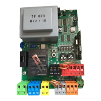
The THALIA control panel comes with standard factory settings. Any change
must be made using the programmer with built-in display or universal handheld
programmer.
The Control unit completely supports the EELINK protocol.
Its main features are:
- Control of 1 or 2 24V BT motors
Note: 2 motors of the same type must be used.
- Electronic torque control with obstacle detection
- Limit switch control inputs based on motor selected
- Separate inputs for safety devices
- Built-in radio receiver rolling code with transmitter cloning.
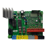
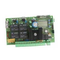
The board has a terminal strip of the removable kind to make maintenance
or replacement easier. It comes with a series of prewired jumpers to make the
installer’s job on site easier.
The jumpers concern terminals: 70-71, 70-72, 70-74. If the above-mentioned
terminals are being used, remove the relevant jumpers.
TESTING
The THALIA panel controls (checks) the start relays and safety devices (photocells)
before performing each opening and closing cycle.
If there is a malfunction, make sure that the connected devices are working
properly and check the wiring.
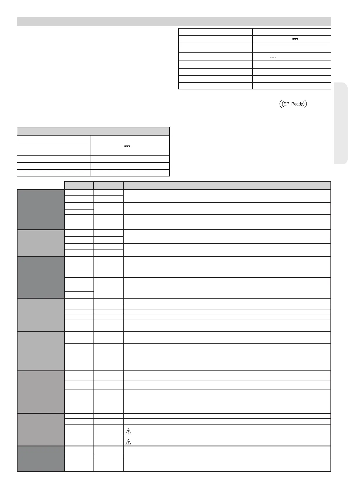
3) TECHNICAL SPECIFICATIONS
Power supply 220-230V 50/60 Hz*
Low voltage/mains insulation > 2MOhm 500V
Operating temperature range -20 / +55°C
Thermal overload protection Software
Dielectric rigidity mains/LV 3750V~ for 1 minute
Motor output current max. 7.5A+7.5A
Motor relay switching current
10A
Maximum motor power 180W + 180W (24V
)
Accessories power supply
24V~ (demand max. 1A)
24V~safe
AUX 0
NO 24V
powered contact (max.1A)
AUX 3
NO contact (24V~/max.1A)
Fuses see Fig. C
N° of combinations 4 billion
Max.n° of transmitters that can be memorized
63
(*other voltages to order)
Usable transmitter versions:
All ROLLING CODE transmitters compatible with
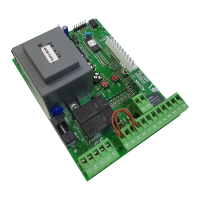
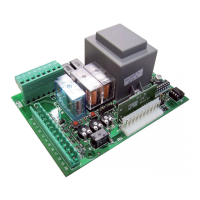
4) TUBE ARRANGEMENT Fi g. A
5) TERMINAL BOARD WIRING Fig. C
WARNINGS - When performing wiring and installation, refer to the standards in
force and, whatever the case, apply good practice principles.
Wires carrying dierent voltages must be kept physically separate from each other,
or they must be suitably insulated with at least 1mm of additional insulation.
Wires must be secured with additional fastening near the terminals, using devices
such as cable clamps.
All connecting cables must be kept far enough away from the dissipater.
WARNING! For connection to the mains power supply, use a multicore cable
with a cross-sectional area of at least 3x1.5mm2 of the kind provided for
by the regulations in force. To connect the motors, use a cable with a cross-
sectional area of at least 1.5mm2 of the kind provided for by the regulations
in force. The cable must be type H05RN-F at least.
Terminal Denition Description
Power supply
L LINE
Single-phase power supply
220-230V 50/60 Hz*
N NEUTRAL
JP5
TRANSF PRIM Transformer primary winding connection, 220-230V.
JP7
JP21 TRANSF SEC
Board power supply:
24V~ Transformer secondary winding
24V= Buer battery power supply
Motor
10 MOT1 +
Connection motor 1. Time lag during closing.
Check connections shown in Fig.E
11 MOT1 -
14 MOT2 +
Connection motor 2. Time lag during opening.
Check connections shown in Fig.E
15 MOT2 -
Aux
20
AUX 0 - 24V
POWERED
CONTACT (N.O.)
(MAX. 1A)
AUX 0 congurable output - Default setting FLASHING LIGHT.
2ND RADIO CHANNEL/ SCA GATE OPEN LIGHT/ COURTESY LIGHT command/ ZONE LIGHT command/ STAIR LIGHT/ GATE
OPEN ALARM/ FLASHING LIGHT/ SOLENOID LATCH/ MAGNETIC LOCK/ MAINTENANCE/ FLASHING LIGHT AND MAINTE-
NANCE. Refer to “AUX output conguration” table.
21
26
AUX 3 - FREE
CONTACT
(N.O.)
(Max. 24V 1A)
AUX 3 congurable output - Default setting 2ND RADIO CHANNEL Output.
2ND RADIO CHANNEL/ SCA GATE OPEN LIGHT/ COURTESY LIGHT command/ ZONE LIGHT command/ STAIR LIGHT/ GATE
OPEN ALARM/ FLASHING LIGHT/ SOLENOID LATCH/ MAGNETIC LOCK.
Refer to “AUX output conguration” table.
27
Limit switch for
ELI 250 BT
VIRGO SMART BT A
ELI BT A35 LS
ELI BT A40 LS
5 wires
41 + REF SWE Limit switch common
42 SWC 1 Motor 1 closing limit switch SWC1 (N.C.).
43 SWO 1 Motor 1 opening limit switch SWO1 (N.C.).
44 SWC 2 Motor 2 closing limit switch SWC2 (N.C.).
45 SWO 2 Motor 2 opening limit switch SWO2 (N.C.).
Limit switch for
PHOBOS N BT
IGEA BT
SUB BT
PHOBOS BT A
KUSTOS BT A VIRGO
SMART BT A
3 wires
42 SW 1
Limit switch control motor 1.
For actuators with single-wire limit switch control.
43 SW 2
Limit switch control motor 2.
For actuators with single-wire limit switch control.
Limit switch for
GIUNO ULTRA BT A20
GIUNO ULTRA BT A50
E5 BT A18
E5 BT A12
40 - REF SWE Limit switch common
42 SW 1 Limit switch control motor 1.
43 SW 2 Limit switch control motor 2.
Limit switch for
ELI BT A35 LS
ELI BT A40 LS
40 - REF SWE Encoder power supply, white cable
41 + REF SWE Encoder power supply, brown cable
42 ENC M1
Engine 1 encoder signal, green cable
Close the jumper JP28
43 ENC M2
Engine 2 encoder signal, green cable
Close the jumper JP29
Accessories
power supply
50 24V-
Accessories power supply output.
51 24V+
52 24 Vsafe+
Tested safety device power supply output (photocell transmitter and safety edge transmitter).
Output active only during operating cycle.
THALIA - 31
D814123 0AA00_01

 Loading...