/
OK OK
stat
vers
password
bft. . .
/
/
Err
OK
01.33
02.01
. . . . .
30.15
OK
0--- 10--
OK
150-
OK
1520 prg
OK OK
P1
P2
P1
P2
P1
P2
P1
P2
OK
0000
/
OK
0000
/
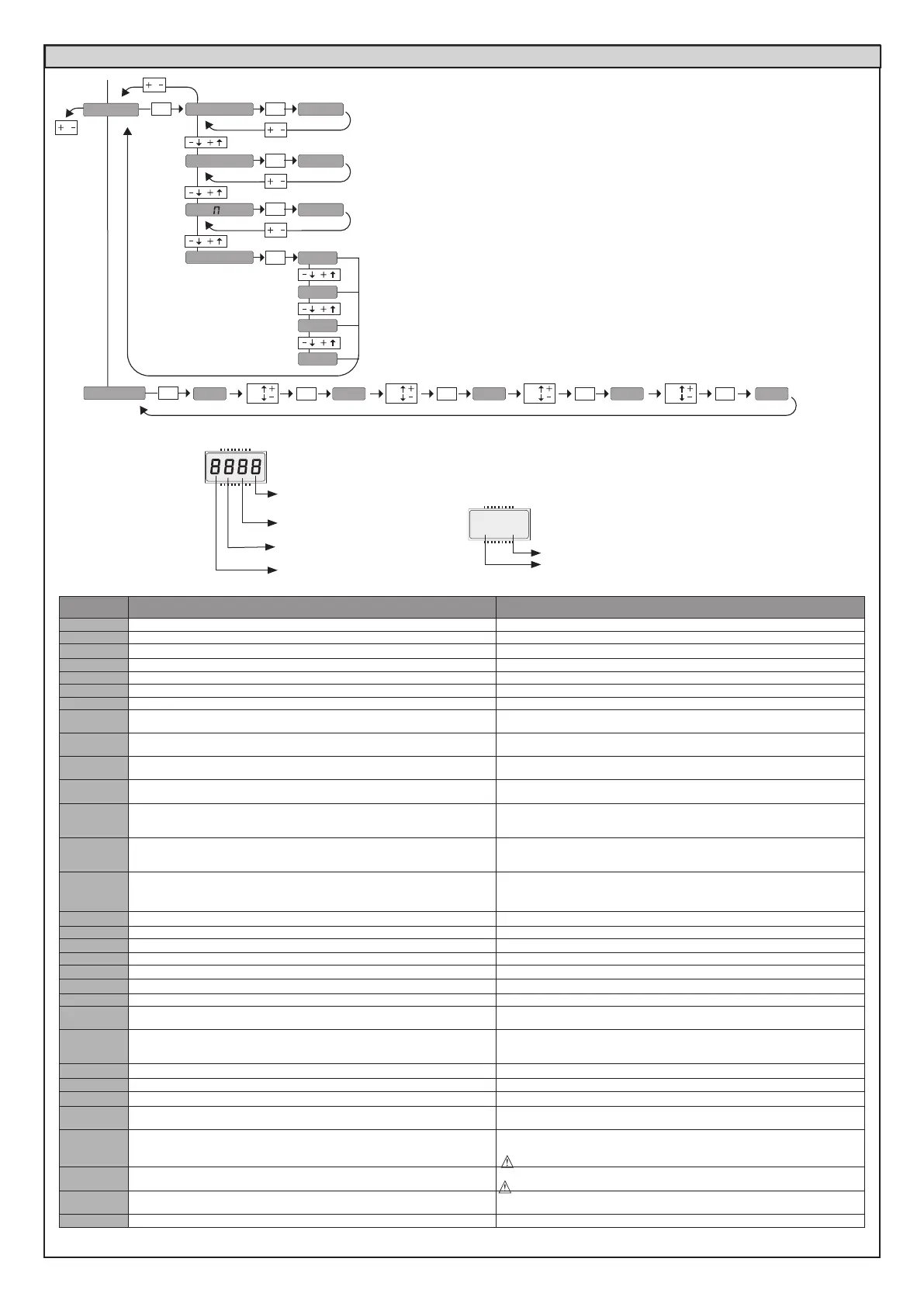
n. cycles
n. re otes
Diagnostics
code
DESCRIPTION NOTES
STRE
START E external start input activated
STRI
START I internal start input activated
OPEN
OPEN input activated
CLS
CLOSE input activated
PED
PED pedestrian input activated
TIME
TIMER input activated
STOP
STOP input activated
PHOT
Activation of PHOT photocell input or, if congured as veried photocell, Activation
of the associated FAULT input
PHOP
Activation of PHOT OP opening photocell input or, if congured as active veried
photocell only when opening, Activation of the associated FAULT input
PHCL
Activation of PHOT CL closing photocell input or, if congured as active veried
photocell only when closing, Activation of the associated FAULT input
BAR
Activation of BAR safety edge input or, if congured as veried safety edge, Acti-
vation of the associated FAULT input
baro
Activation of BAR safety edge input with ACTIVE reversal ONLY WHILE OPENING,
or, if congured as veried safety edge active only while opening, Activation of
the associated FAULT input
barc
Activation of BAR safety edge input with ACTIVE reversal ONLY WHILE CLOSING,
or, if congured as veried safety edge active only while closing, Activation of the
associated FAULT input
SET
The board is standing by to perform a complete opening-closing cycle uninter-
rupted by intermediate stops in order to acquire the torque required for movement.
WARNING! Obstacle detection not active
ER01
Photocell test failed Check photocell connection and/or logic settings
ER02
Safety edge test failed Check safety edge connection and/or logic settings
ER03
Opening photocell test failed Check photocell connection and/or parameter/logic setting
ER04
Closing photocell test failed Check photocell connection and/or parameter/logic setting
er06
8k2 safety edge test failed Check safety edge connection and/or parameter/logic settings
ER07
Opening safety edge test failed Check safety edge connection and/or parameter/logic settings
ER08
Closing safety edge test failed Check safety edge connection and/or parameter/logic settings
ER1x*
Board hardware test error
- Check connections to motor
- Hardware problems with board (contact technical assistance)
ER2x*
Encoder error
- Motor or encoder signal power cables inverted/disconnected or incorrect pro-
gramming (see Fig. E)
- Actuator movement is too slow or stopped with respect to programmed operation.
ER3x*
Reverse due to obstacle - Amperostop Check fo r obstacles in path
ER4x*
Thermal cutout Allow automated device to cool
ER5x*
Communication error with remote devices Check connection with serial-connected accessory devices and/or expansion boards
ER70, ER71
ER74, ER75
Internal system supervision control error.
Try switching the board o and back on again. If the problem persists, contact the
technical assistance department.
ER72
Consistency error of the control unit’s parameters (Logics and Parameters)
Pressing OK the detected settings are conrmed. The board will keep on working
with the detected settings.
The board settings must be checked (Parameters and Logics)
ER73
D-track parameter error
Pressing OK, the board will keep on working with D-track as a default.
An autoset is required
Ersw
Error during limit switch adjustment
Only for E5 BT A18 / E5 BT A12
Motor or encoder signal power cables inverted/disconnected or incorrect
programming. (see Fig. E)
ERf3
Error in the conguration of the logics (SAFE inputs, motor type) Check that the SAFE logic or motor type conguration is correct.
*X= 0, 1, .., 9, A, B, C, D, E, F
Instantaneous force motor 2
Instantaneous force motor 1
35.40
C=
SWC2 motor 2 closing limit
switch input activated
O=
SWO1 motor 1 opening limit
switch input activated
C=
SWC1 motor 1 closing limit
switch input activated
O=
SWO2 motor 2 opening limit
switch input activated
Control unit software version
No total manoeuvres (in hundreds)
No radio control devices memorised
List of last 30 errors
ACCESS MENUS FIG. 1
30 - THALIA
D814123 0AA00_01
 Loading...