ENGLISH
INSTALLATION MANUAL
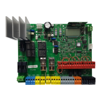
6) MOTOR WIRING Fig. E
7) SAFETY DEVICES
Note: only use receiving safety devices with free changeover contact.
7.1) TESTED DEVICES Fig. F
7.2 CONNECTION OF 1 PAIR OF NONCHECKED PHOTOCELLS FIG. D1
7.3 CONNECTION OF 1 PAIR OF CHECKED PHOTOCELLS FIG. D2
8 CALLING UP MENUS: FIG. 1
8.1) PARAMETERS MENU PARA PARAMETERS TABLE “A”
8.2) LOGIC MENU LOGIC LOGIC TABLE “B”
8.3) RADIO MENU radio RADIO TABLE “C”
- IMPORTANT NOTE: THE FIRST TRANSMITTER MEMORIZED MUST BE
IDENTIFIED BY ATTACHING THE KEY LABEL (MASTER).
In the event of manual programming, the rst transmitter assigns the RECEIVER’S
KEY CODE: this code is required to subsequently clone the radio transmitters.
The Clonix built-in on-board receiver also has a number of important advanced features:
• Cloning of master transmitter (rolling code or xed code).
• Cloning to replace transmitters already entered in receiver.
• Transmitter database management.
• Receiver community management.
To use these advanced features, refer to the universal handheld programmer’s
instructions and to the general receiver programming guide.
8.4 DEFAULT MENU default
Restores the controller’s DEFAULT factory settings. Following this reset, you will
need to run the AUTOSET function again.
8.5 LANGUAGE MENU language
Used to set the programmer’s language on the display.
8.6 AUTOSET MENU AUTOset
•
Launch an autoset operation by going to the relevant menu.
•
As soon as you press the OK button, the “.... .... ....” message is displayed and the control
unit commands the device to perform a full cycle (opening followed by closing), during
which the minimum torque value required to move the leaf is set automatically.
The number of cycles required for the autoset function can range from 1 to 3.
During this stage, it is important to avoid breaking the photocells’ beams and not
to use the START and STOP commands or the display.
Once this operation is complete, the control unit will have automatically set the
optimum torque values. Check them and, where necessary, edit them as described
in the programming section.
WARNING!! Check that the force of impact measured at the points
provided for by standard EN 12445 is lower than the value laid down
by standard EN 12453.
Impact forces can be reduced by using deformable edges.
Warning!! While the autoset function is running, the obstacle detection
function is not active. Consequently, the installer must monitor the
automated system’s movements and keep people and property out
of range of the automated system.
8.7)INSTALLATION TEST PROCEDURE
1. Run the AUTOSET cycle (*)
2. Check the impact forces: if they fall within the limits (**) skip to point 10 of the
procedure, otherwise
3. Where necessary, adjust the speed and sensitivity (force) parameters: see
parameters table.
4. Check the impact forces again: if they fall within the limits (**) skip to point 10
of the procedure, otherwise
5. Apply a shock absorber prole
6. Check the impact forces again: if they fall within the limits (**) skip to point 10
of the procedure, otherwise
7. Apply pressure-sensitive or electro-sensitive protective devices (such as a
safety edge) (**)
8. Check the impact forces again: if they fall within the limits (**) skip to point 10
of the procedure, otherwise
9. Allow the drive to move only in “Deadman” mode
10. Make sure all devices designed to detect obstacles within the system’s operating
range are working properly
(*) Before running the autoset function, make sure you have performed all the
assembly and make-safe operations correctly, as set out in the installation
warnings in the drive’s manual.
(**) Based on the risk analysis, you may nd it necessary to apply sensitive
protective devices anyway
8.8) LIMIT STOP ADJUSTMENT MENU (REG. FC)
Used to adjust the limit stops for motors equipped with encoder; moreover,
for motors equipped with independent limit stop wiring harness allows the
correct positioning of the leaf for the subsequent limit stop adjustment. For
motors not specied, the menu is not active and the message” unavailable” is
shown on the display
NOTE: these manoeuvres are performed in person preset mode, at slow speed,
without the intervention of the safety devices.
8.8.1) GIUNO ULTRA BT A20, GIUNO ULTRA BT A50
Using the „+/-” buttons on the display, bring the leaf in the desired position. To
adjust the limit stops, refer to the settings for limit stop adjustment provided in
the GIUNO ULTRA motor manual.
8.8.2) E5 BT A12, E5 BT A18
Using the „+/-” buttons on the display, bring the leaf in the position indicated
by the display (opening or closing). Once the desired position is reached,
conrm the position by pressing the OK button. For E5 motors, the leaf can be
manually positioned close to the limit stops by pushing the gate; then move
the gate using the „+/-” button until it is against the mechanical stopper. To
conrm the position, or use the OK button or the radio control (previously
stored).
9) CLOSING LIMIT SWITCH PRESSURE Fig. G Ref. A-B
OPENING DIRECTION Fig. E
10) CONNECTION WITH EXPANSION BOARDS AND UNIVERSAL HANDHELD
PROGRAMMER VERSION> V1.40 (Fig. H) Refer to specic manual.
11) U-LINK OPTIONAL MODULES
Refer to the U-link instructions for the modules.
The use of some models causes lowered radio capacity. Adjust the system using an
appropriate antenna tuned to 433MHxz.
12) SOLENOID LOCK Fig. I
SOLENOID LOCK
WARNING: In the case of leaves longer than 3m, it is essential to install
a solenoid lock.
Fig. I shows a sample connection of an ECB 24V~ solenoid latch connected to
the THALIA control panel.
In order to control the solenoid lock, the THALIA panel needs a special board
mod. ME BT.
13) RESTORING FACTORY SETTINGS (Fig.J)
WARNING: this operation will restore the control unit’s factory settings and all
transmitters stored in its memory will be deleted.
WARNING! Incorrect settings can result in damage to property and injury to
people and animals.
- Cut o power to the board (Fig.J ref.1)
- Open the Stop input and press the - and OK keys together (Fig.J ref.2)
- Switch on the board’s power (Fig.J ref.3)
- The display will read RST; conrm within 3 sec. by pressing the OK key (Fig.J ref.4)
- Wait for the procedure to nish (Fig.J ref.5)
- Procedure nished (Fig.J ref.6)
WARNING! Incorrect settings can result in damage to property and injury to people
and animals.
WARNING: Check that the force of impact measured at the points
provided for by standard EN 12445 is lower than the value laid down
by standard EN 12453.
Impact forces can be reduced by using deformable edges.
For best results, it is advisable to run the autoset function with the motors idle (i.e.
not overheated by a considerable number of consecutive operations).
Safety input conguration
SAFE logic=9 Input congured as Bar op, safety edge with active inversion only while opening, if activated while closing, the automation stops (STOP) (Fig. F, ref. 3).
Allows connecting devices not tted with supplementary test contact. The operation while opening causes the movement to be reversed for 2 seconds, the operation while closing causes the
automation to stop. If not used, leave jumper inserted.
SAFE logic=10 Input congured as Bar op test, safety edge checked with active inversion only while opening, if activated while closing, the automation stops (STOP) (Fig. F, ref. 4).
Activates testing safety edges when starting operation. The operation while opening causes the movement to be reversed for 2 seconds, the operation while closing causes the automation to stop.
SAFE logic=11 Input congured as Bar 8k2 op, 8k2 safety edge with active inversion only while opening, if activated while closing, the automation stops (STOP) (Fig. F, ref. 5).
The operation while opening causes the movement to be reversed for 2 seconds, the operation while closing causes the automation to stop.
SAFE logic=12 Input congured as Bar cl, safety edge with active inversion only while closing, if activated while opening, the automation stops (STOP) (Fig. F, ref. 3).
Allows connecting devices not tted with supplementary test contact. The operation while closing causes the movement to be reversed for 2 seconds, the operation while opening
causes the automation to stop. If not used, leave jumper inserted.
SAFE logic=13 Input congured as Bar cl test, safety edge checked with active inversion only while closing, if activated while opening, the automation stops (STOP) (Fig. F, ref. 4).
Activates testing safety edges when starting operation. The operation while closing causes the movement to be reversed for 2 seconds, the operation while opening causes the automation to stop.
SAFE logic=14 Input congured as Bar 8k2 cl, safety edge with active inversion only while closing, if activated while opening, the automation stops (STOP) (Fig. F, ref. 5).
The operation while closing causes the movement to be reversed for 2 seconds, the operation while opening causes the automation to stop.
(*) If “D” type devices are installed (as dened by EN12453), connect in unveried mode, foresee mandatory maintenance at least every six months.
THALIA -
33
D814123 0AA00_01
 Loading...