SW-Stahl und Werkzeugvertriebs GmbH Tel. +49 (0) 2191 / 46438-0
F 56 essartS resukreveL ax +49 (0) 2191 / 46438-40
ed.lhatsws@ofni :liaM-E diehcsmeR 79824-D
Instruction Manual
BGS technic KG
Bandwirkerstr. 3
D-42929 Wermelskirchen
Tel.: 02196 720480
Fax.: 02196 7204820
mail@bgs-technic.de
www.bgstechnic.com
© BGS technic KG, Copying and further use not allowed
ACTIVATE THE COMPONENTS WITH NEGATIVE VOLTAGE ONLY
Apart from applying the positive voltage, technician can also
use this unit to provide negative voltage to the components.
The procedures are as follow:
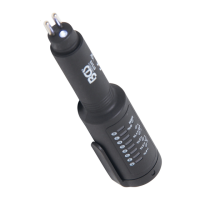
1. Contact its tip to the negative pole of the component; at
this stage, the red LED should be on if the component
working correctly.
2. Push the polar switch backward and release it quickly. If
the LED goes from red to green, you may proceed further
test. If the green LED goes off or the circuit breaker of the
short circuit protection tripped, it means it has overloaded.
This may cause by the following reasons:
1. The component is short circuit or it has been
connected to the ground/ negative pole directly.
2. The component is a high current component.
If the circuit breaker of the short circuit protection has tripped,
it will auto-rest within no more than 60 seconds.
IMPORTANT
Please operate this function with schematic and correct testing procedure because applying
voltage arbitrarily may cause damage to components. Use tip to apply negative voltage, which
can be helpful to diagnose the components.
When applying current to the components, please push the switch before contact the tip with the
components. In this case, the arcing will take place between the tip and the component instead of
the switch. And so it can increase the life time of the switch.
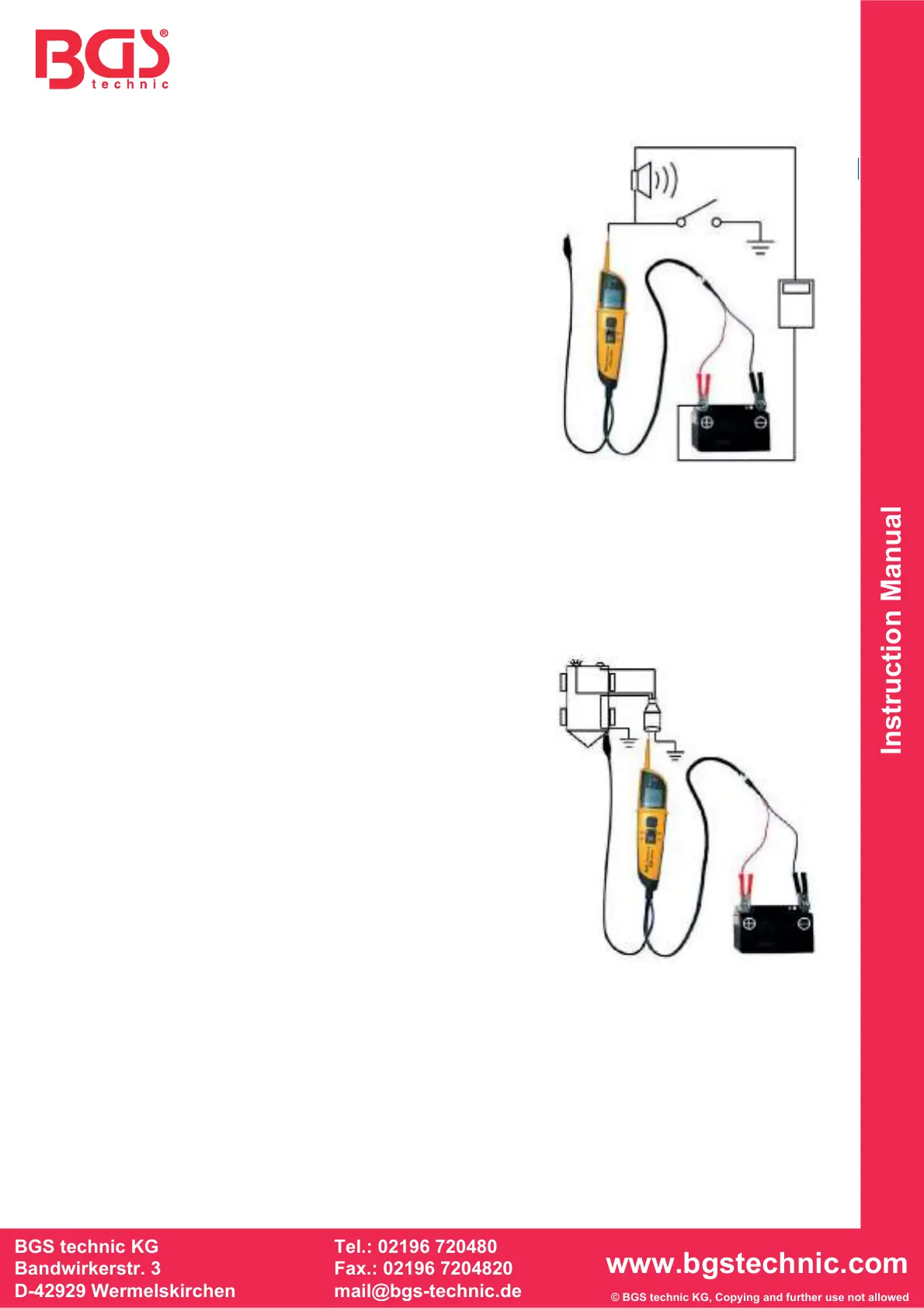
TRAILER LIGHT TEST
To test the trailer light, you need to follow the procedure:
1. Connect the ground test lead to trailer ground.
2. Probe the tip to the outlet of the trailer; push the polar
switch forward, then technician can diagnose the function
of the trailer light.
V
OLTAGE TEST
Technician can also use this unit assisting with ground test lead to test the voltage of the circuit.
However, during the voltage test, please do not push the polar switch.
1. If probe tip is floating (not contacting a circuit), the red and green LED turn off.
2. If it contact the probe tip to a positive circuit. The red positive sign “+” LED will light and the
voltmeter displays the voltage reading within 1/10 of a volt.
3. If it contact the probe tip to a negative circuit. The green negative sign “-“ LED will light.