SW-Stahl und Werkzeugvertriebs GmbH Tel. +49 (0) 2191 / 46438-0
F 56 essartS resukreveL ax +49 (0) 2191 / 46438-40
ed.lhatsws@ofni :liaM-E diehcsmeR 79824-D
Instruction Manual
BGS technic KG
Bandwirkerstr. 3
42929 Wermelskirchen
Tel.: 02196 720480
Fax.: 02196 7204820
mail@bgs-technic.de
www.bgstechnic.com
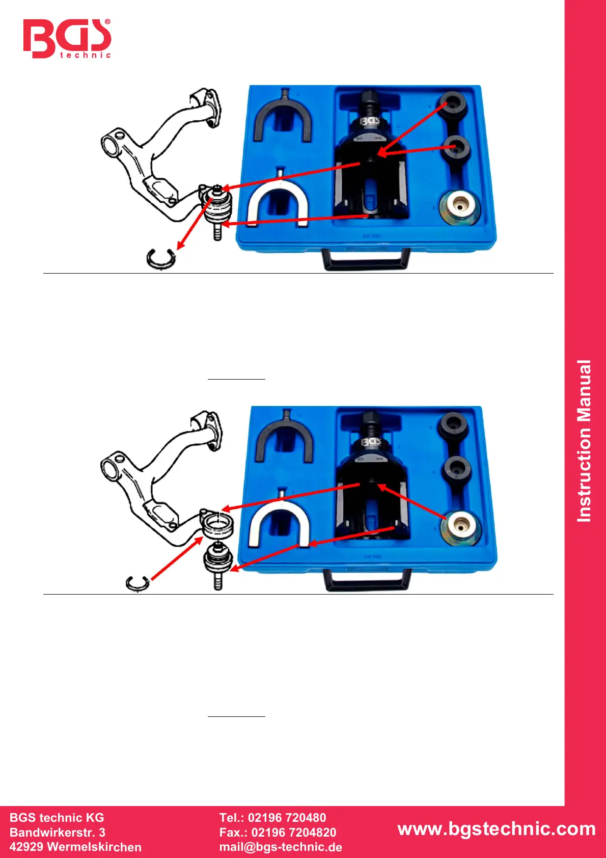
INSTRUCTION Disassembly
1. Disassemble all axle components until the upper joint is fully accessible.
2. Remove the locking ring (S) before applying the tool.
3. Choose suitable pressure plate (4) or (5) – it must fit onto the ball joint’s cone – insert into puller.
4. Insert reducing fork (6) into the lower part of the puller if necessary – reducing fork must fit
exactly onto the suspension arm.
5. Tighten the puller by operating the spindle (2) and check the puller for a proper alignment.
6. Tighten the spindle with a suitable wrench or ratchet until the ball joint is completely pressed out.
Caution: The spindle (2) is not suitable
for impact wrenches.
INSTRUCTION Assembly
1. Clean the ball joint’s borehole before the assembly.
2. Insert pressure plate (3) into puller.
3. Insert reducing fork (7) into lower part of the puller (1), reducing fork must fit exactly onto the ball
join.
4. Apply ball joint to the suspension arm.
5. Tighten the puller by operating the spindle (2) and check the puller for a proper alignment.
6. Tighten the spindle with a suitable wrench or ratchet until the ball joint fits completely onto the
suspension arm. Important: You must install a new locking ring (S) after the assembly.
Caution: The spindle (2) is not suitable
for impact wrenches.
S
S
6
7
5
4
3
2
1
6
7
3
4
5
1
2