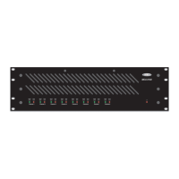
6
BRIDGING / REMOTE CONTROL
BRIDGING
Bridge DIP switches allow the adjacent odd/even numbered channels to be bridged together
in pairs, for a higher, combined output power (see Bridge on previous page). When a pair of
channels are bridged, their wattage is combined, but the minimum load increases to 8 ohms
(MCA 8050 = 100 watts @ 8 ohms; MCA 8150 = 300 watts @ 8 ohms). Bridge disables the
even numbered input, and applies the odd numbered input signal to both amplifier channels.
From the factory, Bridge is bypassed (switches up). To assign Bridge to a pair of channels,
move the related switch to the down position. Connect the source signal to the odd
numbered input channel, connect the positive speaker line to the (+) output terminal of the
odd
numbered channel, and connect the negative speaker line to the (+) output terminal of
the even
numbered channel (see diagram on right). NOTE: Only adjacent odd/even
numbered channels, which share a common Bridge switch, can be bridged. When channels
are bridged, the minimum load is increased to 8 ohms. The negative (-) output terminals on
bridged channels are not
used (no connection). For remote control of a bridged pair of
channels, only the odd numbered input channel requires control (see Remote Control below).
2
12
outputs
level
signal / peak
signal / peak
level
input input
HPF
HPF
OFF
OFF
OFF
BRIDGE
source
signal
speaker
positive
speaker
negative
1
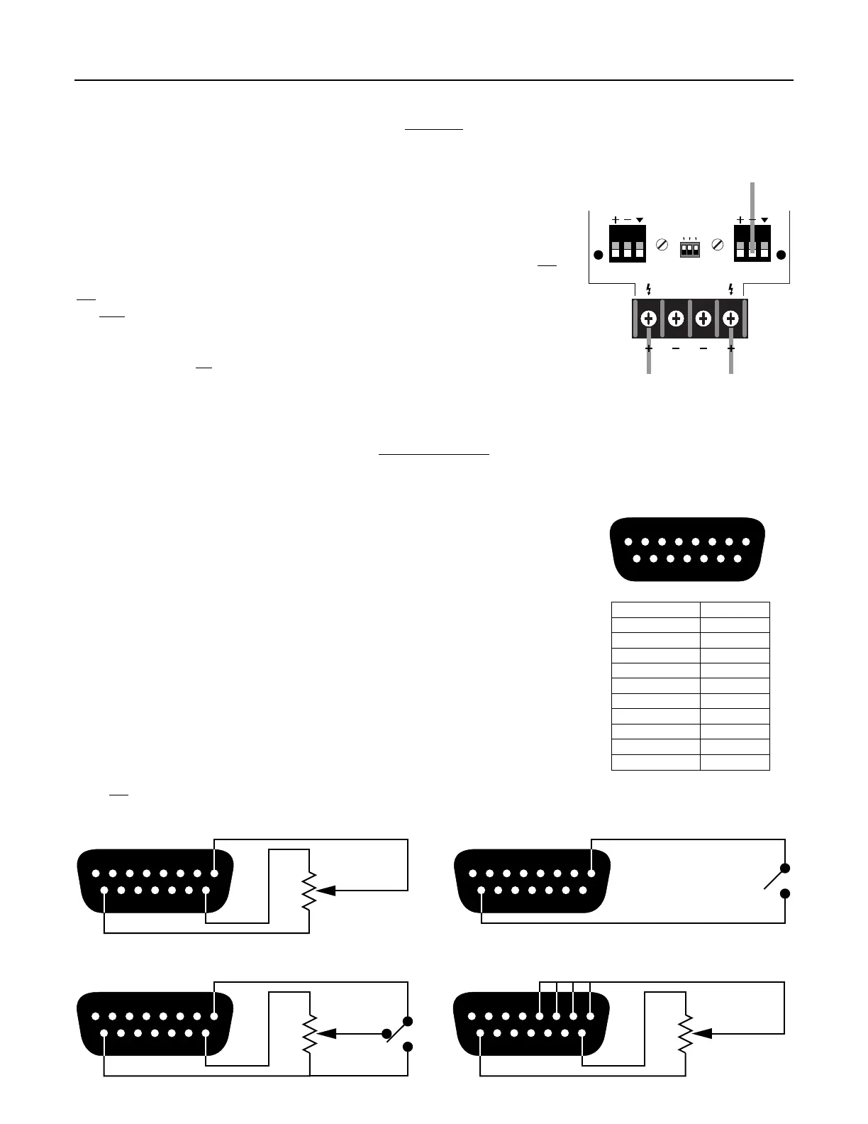
REMOTE CONTROL
The 15-pin Sub-D (female) Remote Control connector provides terminals for remote
level/mute control of Channels 1~8 (see diagram & table on right). A variable control voltage
(0~+10 VDC) is used to control levels (+10 VDC = unity gain; 0 VDC = off). Remote Control
provides +10V and ground terminals (for use with potentiometers), but external ‘ramp’
voltage devices, such as a BIAMP DRI, may be used instead (see Applications on pg. 8).
Potentiometers should be 25k
Ω linear taper, and are wired with high to +10V, low to ground,
and wiper to the desired channel terminal(s). See examples below. The wiper of a single
potentiometer may be wired to multiple control terminals (to control a group of channels).
However, wipers from multiple potentiometers should not be connected to a single control
terminal (undesirable interaction). Switches, Logic Outputs, or other contact-closures can be
used to mute channels, by simply shorting the associated control terminal(s) to ground. A
switch may be wired to multiple control terminals (to mute a group of channels). Multiple
switches may be wired to a single control terminal, but wiring multiple switches to multiple
control terminals would require a diode matrix. The combination of a potentiometer & a
switch can be used to perform level adjustment & muting, or to provide an adjustable amount
of mute attenuation. NOTE: Remote controls simply decrease volume from a maximum,
which is established with the channel Level controls (see Level on previous page). When
using a pair of channels in 'bridged' mode (see Bridging above), apply Remote Control only
to the odd
numbered input channel.
remote control pin number
channel 1
channel 2
channel 3
channel 4
channel 5
pin #1
pin #2
pin #3
pin #4
pin #5
pin #6
pin #7
pin #8
pin #9
channel 6
channel 7
channel 8
+10V
pins #10~15
ground
12345678
9
101112131415
remote control
12345678
9
101112131415
high
low
wiper
high
low
wiper
high
low
wiper
Channel 1 Level
12345678
9
101112131415
Channels 1~4 Group Level
12345678
9
101112131415
Channel 1 Mute
12345678
9
101112131415
Channel 1 Level & Mute
 Loading...