User’s Manual UPSI-2401
20
English
User’s Manual UPSI-2401
21
English
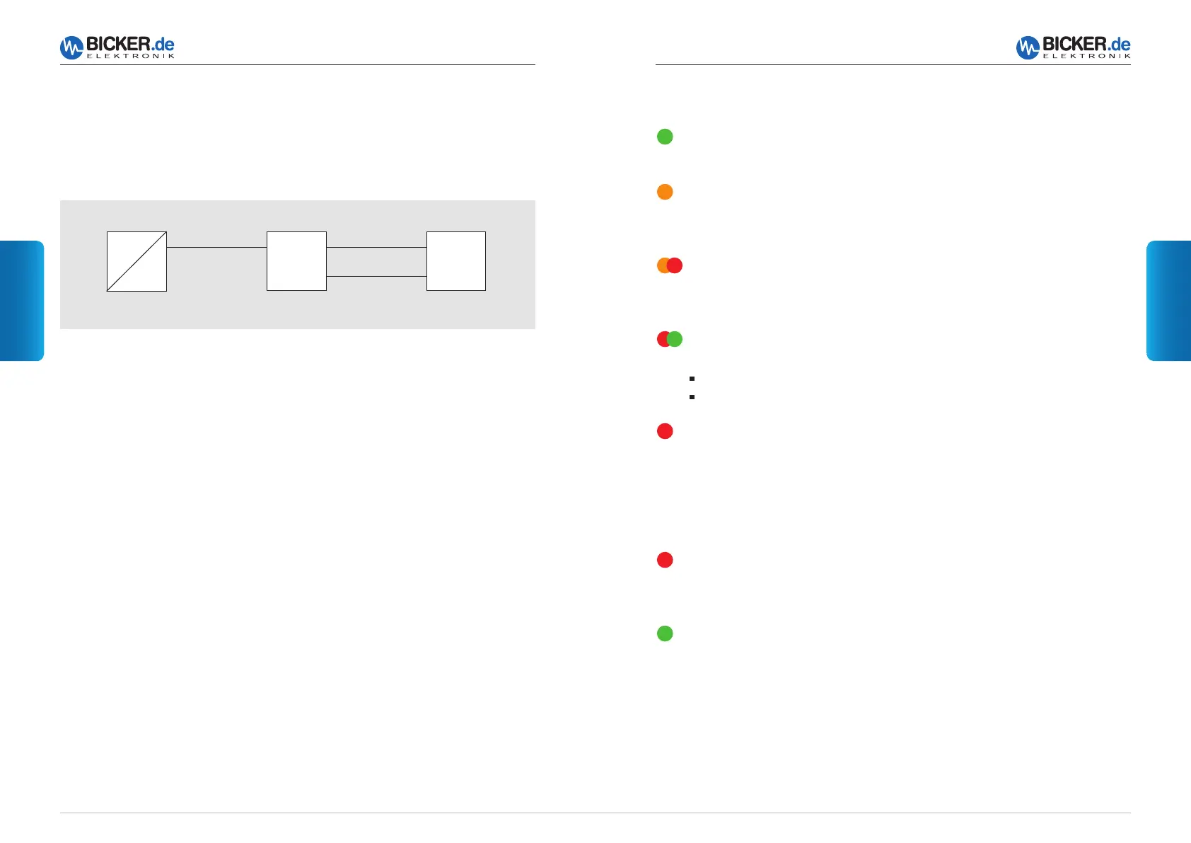
4 LED Display
Power ok
The LED is green as long as an input voltage (>20 V DC) is present.
Power fail (mains power failure)
The LED turns to orange as soon as the DC UPS UPSI-2401 switches
to battery mode (input voltage <20 V DC).
Battery low
The LED flashes red/orange in battery mode when the capacitance of the
internal battery pack decreases (battery voltage dropping to <21 V).
Battery fail (Battery defect)
The LED flashes red/green
when the internal battery pack is discharged or defect.
when the battery supply line or fuse is defect.
Short circuit at output
Remove short-circuit or overload at the output.
UPS can be re-started by disconnecting from the mains.
LED Display at switch to UPS mode and reduction of input voltage to 20 V…17 V
Red flashing
The LED is flashing red when the UPS switches off in case of a defect battery, fuse
or not connected battery.
Green flashing
The LED is flashing green when the UPS switches off approx. 10 to 15 seconds after
receipt of the shutdown signal (DSuB) and activation of the power sensor (<10 W)
resp.
3 Functional Description
In case of a mains voltage failure the DC UPS UPSI-2401 supplies the connected
consumer load with DC voltage from the internal battery pack. Via LED display the status
is visualised. Signals can be informed to a connected PC via interface.
3.1 Mains Mode
In mains mode a voltage source at the input line supplies 24 V DC. This voltage minus
app. 0.45 V DC is provided directly at the consumer load (e. g. PC). The internal bat-
tery pack is charged by the UPSI-2401. The LED is green and the interface signalises
“Power ok“. App. every 10 minutes a battery test is carried out. In case of a defect
battery pack or a cable brake, the LED flashes red/green.
3.2 Battery Mode
If the supply voltage drops below the switch-over threshold at the input of the
DC UPS, the UPSI-2401 takes over supplying the connected consumer loads.
The LED is orange and the interface signalises “Power Fail“. When the capa-
citance of the internal battery pack decreases (battery voltage dropping to
<21 V), the interface signalises “Battery Low“. The LED flashes red/orange. The DC UPS
UPSI-2401 can be switched off by an impulse at the “Shutdown“ input.
AC
DC
DC UPS
UPSI-2401
Consumer
load (PC)
Interface
Source:
e. g. AC/DC power supply
 Loading...