©2013 DELTA T CORP. ALL RIGHTS RESERVED. 003927 REV. I
5
HAIKU
®
by BIG ASS FANS
HAIKU WALL CONTROL (CONT.)
Step 8. Test the fan(s)
Reapply AC power, and then turn on the fan(s) using the wall control to test the DIP switch address. If the wall
control does not operate the fan(s) due to interference with other radio frequency devices, turn o power to
the fan(s) and wall control, select a dierent address on the wall control, and then set the matching address
on the RF board(s). Reapply power and retest. Repeat until an appropriate address is determined.
Power to the fan(s) and wall control must be turned o during address changes. If power is on during
an address change, the change may not be accepted.
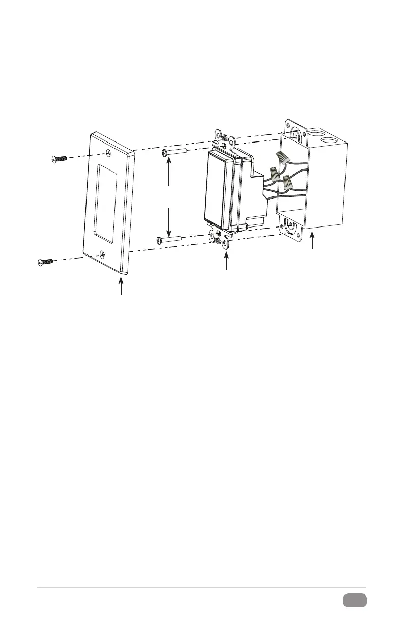
Wall Control
Junction Box
(in wall)
Wall Plate
#6-32
Screw
Step 7. Install the wall control
Install the wall control with the provided #6-32 x 7/8” screws in a location within 20 ft (6 m) of the fan. Do not
overtighten the screws. Install the wall plate using the screws provided with the wall plate. Note: If your wall
control kit does not include a wall plate, Big Ass Fans recommends using a Decora® wall plate. Other brands
may not be compatible.
Step 9. Install lower cover or (optional) LED light kit
If you purchased the Haiku LED light kit, proceed to the instructions included with the kit. If you did not
purchase the LED light kit, proceed to the step for installing the lower cover in the complete Haiku Installation
Guide.
 Loading...