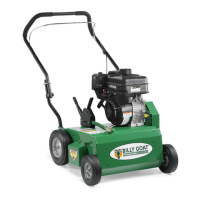
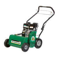
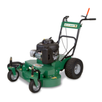
OVERSEEDER/POWER RAKE Owner’s Manual
Part No 350412 350412_E_HI
MAINTENANCE
NOTE: Items in ( ) can be referenced in the Parts Illustrations and Parts Lists on pages 11-16.
PERIODIC MAINTENANCE
Periodic maintenance should be performed at the following intervals:
Inspect for loose, worn or damaged parts
Engine (See Engine Manual)
Inspect and clean engine air filter
Oil height adjustment linkage
FLAIL BLADE WEAR
1. Wait for engine to cool and disconnect spark plug.
2. Close fuel valve on engine (if available).
3. Securely gain access to the underside of the machine.
4. Inspect blades for wear, and immediately replace any bent or cracked blades.
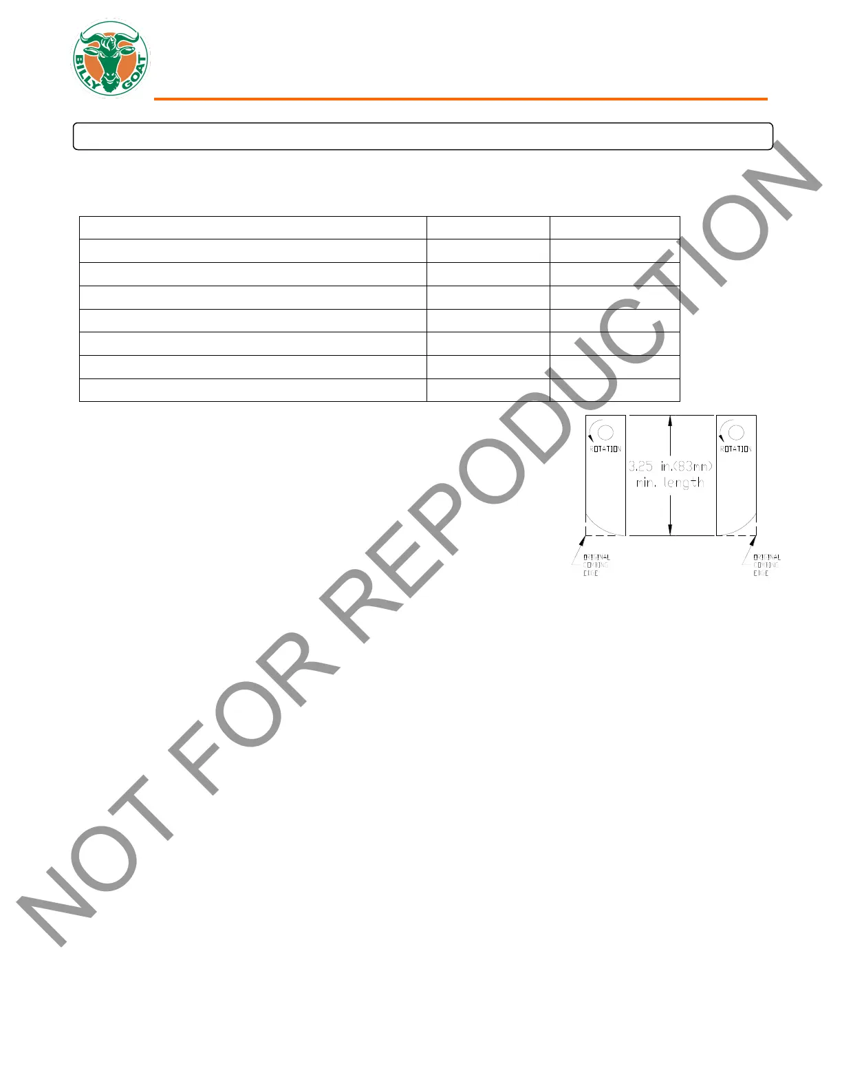
Measure the overall length of the blade. (See Fig. 9)
5. If blades measure less than 3.25"(83 mm) in overall length they must be
replaced. NOTE: We recommend replacing all the flails at once.
SLICING BLADE WEAR
1. Wait for engine to cool and disconnect spark plug.
2. Close fuel valve on engine (if available).
3. Lean unit back onto lower handles and secure in place.
4. Inspect blades for wear, and immediately replace any bent or cracked blades. Measure the overall length of the blade
from the center of the attachment bolt to the tip of the worn blade.
5. If blades measure less than 3"(76 mm) in length they must be replaced. NOTE: We recommend replacing all the blades
at once.
ROTATING FLAIL REEL END TO END
To maximize flail blade life and performance the reel can be rotated end to end periodically to provide a fresh lead cutting edge.
Takes approx. 20 min. and requires 1/2" and 9/16" socket wrenches with extension bar.
1. Wait for engine to cool and disconnect spark plug.
2. Close fuel valve on engine (if available).
3. Lean unit back onto lower handles and secure in place.
4. Remove seven lock nuts (item 62 & 40) holding the belt and shaft guards (item 21 & 22) in place. It is necessary to lower
the height adjust lever to reach the locknuts on the guards. Remove the guards.
5. Remove the drive belt (item 9) by "walking" it out of the groove on the reel pulley (item 2).
6. Remove the four lock nuts (item 60) and washers (item 68) holding the bearings (item 23) to the frame of the unit.
7. The reel is now free from the machine. Slide the reel down and out of the machine.
8. Remove the capscrew (item 71), lock washer (item 57), reel pulley (item 2), key (item 42), and reel spacer (item 10) from
the end of the reel.
9. Rotate the reel end to end, and re-install these items on the opposite end of the reel.
10. Re-install the reel in reverse order of removal. Re-install the guards in reverse order of removal.