4
Sales and Service Through a Nationwide Network of Industrial Distributors.
Customer Service in USA / 1-800-992-4657
Technical Support in USA / 1-888-992-4657
195 Internationale Blvd.
Glendale Heights, IL 60139 Part Sheet 2340R-6 Printed in USA 1/01, All Rights Reserved
2340R-6 Revisions: Updated graphic standards; contact information. Reset all type and
diagrams.
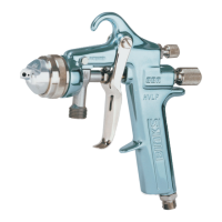
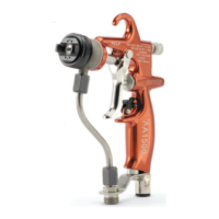
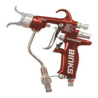
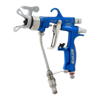
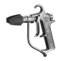
Binks AIRLESS 1 SPRAY GUN MAINTENANCE INSTRUCTIONS
See High Pressure Warning Statement, page 3.
TO CLEAN NOZZLE TIP
1. Turn safety knob (18) 90º to disengage trigger (21).
2. Shut off power supply to pump and release pressure
from gun. Remove gun from hose.
3. Remove tip guard assembly (1), nozzle tip and
gasket (2).
4. Submerge nozzle tip in solvent to remove dry
coating.
5.
Blow air through nozzle from front end to eject stuck
particles. Hold up to light to assure orifice is clear.
6. Reassemble in reverse order.
TO REPLACE CARTRIDGE ASSEMBLY (16)
1. Shut off power supply to pump and release pressure
from gun. Remove gun from hose.
2.
Remove screw (19), safety knob (18) and guide (17).
3. Unscrew gland nut.
4. Pull cartridge assembly (11) out from back of gun.
5. Make sure inside of gun is clean.
6. Reinsert cartridge assembly (11) (of step 4) into
position through back of gun body assembly.
Tighten gland nut.
7. Reassemble items 15 through 19.
TO REPLACE PACKING (17)
1. Remove cartridge assembly following steps 1-4
under “To Replace Cartridge Assembly.”
2. Locate slot in packing gland (10), pry apart and
push off.
3. Replace with new packing gland, and reassemble.
TO ADJUST PACKING GLAND (10)
1. Shut off power supply to pump and release pressure
from gun. Remove gun from hose.
2. Use a 7/16" open-end wrench to turn gland nut (18)
clockwise to eliminate any leakage at gland.
3. If sluggish trigger operation is noted, turn gland nut
counterclockwise in 1/16 turn increments until drag
is eliminated.
4. If leakage cannot be stopped without excessive drag
on trigger, replace packing.
TO REPLACE SEAT (6)
1. Shut off air or power supply to pump and release
pressure from gun. Remove gun from hose.
2. Remove tip guard assembly (1) and nozzle tip and
gasket (2).
3. Remove nut diffuser and attached parts (3, 4, 5, 6,
& 7). Unscrew seat retainer (7) from nut diffuser (3).
Seat should drop out.
4. Reassemble in reverse order.
54-2378 54-1835
54-1836
CAUTION
1. Use care when handling nozzle tips to avoid dropping.
Tips are made of tungsten carbide and are brittle.
2. Never use metal probes to clean nozzle tips.
3. Excessive fluid pressure will cause undue wear.
!
NOTE
Use of diffuser/filter assembly will eliminate most tip clog-
ging problems.
DIFFUSER ASSEMBLY ACCESSORY
Reduces fluid velocity to minimize tip wear and make tip
removal safer. Also to aid fluid filtration. Order 54-2229
nylon gasket with set-up, described below.
54-2378 nut for use with 54-1835 (.005) or 54-1836
(.009) edge type filter.
 Loading...