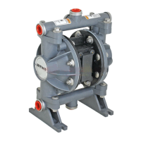
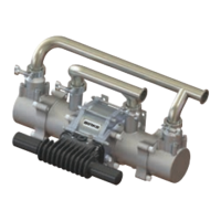
Model 41-818831
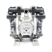
Conductive Acetal Ball Valve Pump
Table of Contents
Engineering Data and Temperature Limitations .......................................................1
Warranty Information ................................................................................................1
Performance Curve ..................................................................................................2
Dimensions ...............................................................................................................3
Metric Dimensions ....................................................................................................3
Principle of Pump Operation.....................................................................................4
Installation and Start-up............................................................................................4
Air Supply .................................................................................................................4
Air Valve Lubrication .................................................................................................4
Air Line Moisture.......................................................................................................4
Air Inlet and Priming .................................................................................................4
Between Uses ..........................................................................................................4
Troubleshooting .......................................................................................................5
Important Safety Information ....................................................................................6
Composite Repair Parts Drawing .............................................................................8
.....................................................8
Available Service and Conversion Kits .....................................................................8
Composite Repair Parts List .....................................................................................9
Air Valve Assembly Drawing ...................................................................................10
Air Valve Assembly Parts List .................................................................................10
Air Valve Servicing ..................................................................................................11
Pilot Valve Servicing ...............................................................................................12
Intermediate Assembly Drawing and Servicing ......................................................13
Check Valve Drawing .............................................................................................14
Check Valve Servicing ............................................................................................14
Diaphragm Service Drawing, with Overlay .............................................................15
Diaphragm Servicing ..............................................................................................16
Overlay Diaphragm Servicing ................................................................................16
Pumping Hazardous Liquids...................................................................................17
Converting the Pump for Piping the Exhaust Air ....................................................17
Exhaust Conversion Drawing .................................................................................17
Converted Exhaust Illustration................................................................................17
Grounding the Pump ..............................................................................................18
EC Declaration of Conformity - Machinery .............................................................19
EC Declaration of Conformity - ATEX .....................................................................20
..............................................................................21
II 2 G c T5
II 3/2 G c T5
II 2 D c T100°c
SERVICE & OPERATING MANUAL
Original Instructions
Part Sheet 77-2995