EN
77-2841-R6 (6/2018) 3 / 12 www.carlisleft.com
The first requirement for a good resultant finish is the proper
handling of the gun. The gun should be held perpendicular to
the surface being covered and moved parallel with it.
The stroke should be started before the trigger is pulled,
and the trigger should be released before the stroke is ended.
This gives accurate control of the gun and material.
The distance between the gun and surface should be 6 to 10
inches depending on material and atomizing pressure. The
material deposited should always be even and wet. Lap each
stroke over the preceding stroke to obtain a uniform finish.
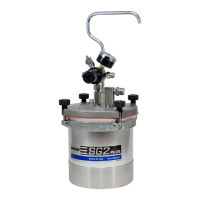
Set up the SG-2 Plus
TM
with the CONVENTIONAL
or HVLP gun along with at least 5 ft. of air and fluid hose.
Attach air hose from extractor to air inlet on handle of steadi-
grip assembly. Pour paint into canister with liner. Re-attach lid to
canister and firmly tighten four knobs over canister lid. Set air
pressure from air regulator mounted on extractor and fluid pres-
sure by adjusting fluid pressure adjustment knob on cup handle.
SETUP AND OPERATION
Refer to “TYPICAL INSTALLATION” drawing below
SPRAY TECHNIQUE
WARNING
Chlorinated solvents and aluminum are incompatible and will
cause an adverse chemical reaction, possibly resulting in bodi-
ly injury. Under NO circumstances should chlorinated sol-
vents be used with the “SG2 Plus” pressure cup with agita-
tor (80-601). With the standard “SG2 Plus” pressure cup, use
chlorinated solvents only when using plastic liner (80-356).
!
NOTE
Before refilling canister with paint, shut off air supply to the
cup and release pressure from canister by rotating pressure
relief knob counterclockwise.
CAUTION
Do not exceed 100 PSIG input air pressure into the cup.
Excessive pressure could damage components.
!
RIGHT
WRONG
6 to 12 inches
Start
Stroke
Pull
Trigger
Release
Trigger
End of
Stroke
Coating should be even
and wet when spraying
Coating will
be light at
this point
Coating will
be heavy at
this point
Travel of Gun
TYPICAL INSTALLATION
Air Hose
Air
Regulator
Fluid Pressure
Control
Air Hose
Air Controller
3/8 NPS (m)
Spray Gun
Fluid Inlet
Fluid Hose
3/8 NPS (m)
Fluid Outlet
Oil and
Water
Extractor