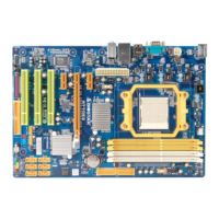
EasyManua.ls Logo

Biostar A770E3

Biostar A770E3
49 pages
To Next Page IconTo Next Page
Loading...
A770E3 Setup Manual
FCC Information and Copyright
This equipment has been tested and found to comply with the limits of a Class
B digital device, pursuant to Part 15 of the FCC Rules. These limits are designed
to provide reasonable protection against harmful interference in a residential
installation. This equipment generates, uses, and can radiate radio frequency
energy and, if not installed and used in accordance with the instructions, may
cause harmful interference to radio communications. There is no guarantee
that interference will not occur in a particular installation.
The vendor makes no representations or warranties with respect to the
contents here and specially disclaims any implied warranties of merchantability
or fitness for any purpose. Further the vendor reserves the right to revise this
publication and to make changes to the contents here without obligation to
notify any party beforehand.
Duplication of this publication, in part or in whole, is not allowed without first
obtaining the vendor’s approval in writing.
The content of this user’s manual is subject to be changed without notice and
we will not be responsible for any mistakes found in this user’s manual. All the
brand and product names are trademarks of their respective companies.

Other manuals for Biostar A770E3

Questions and Answers:

Biostar A770E3 Specifications

General IconGeneral
BrandBiostar
ModelA770E3
CategoryMotherboard
LanguageEnglish

Summary

FCC Information and Copyright

Chapter 1: Introduction

1.1 Before You Start

Essential preparation steps before installing the motherboard.

1.2 Package Checklist

List of components included in the motherboard package.

1.3 Motherboard Features

1.4 Rear Panel Connectors

Rear Panel Connectors

Diagram and description of the motherboard's rear panel ports.

1.5 Motherboard Layout

Motherboard Layout

Visual representation of motherboard components and connectors.

Chapter 2: Hardware Installation

2.1 Installing Central Processing Unit (CPU)

Step-by-step guide for installing the CPU onto the motherboard.

2.2 Fan Headers

Fan Headers

Details on connecting CPU and system fans to motherboard headers.

2.3 Installing System Memory

A. DDR3 Modules

Instructions for installing DDR3 memory modules into DIMM slots.

B. Memory Capacity

Information on supported memory capacities and DIMM configurations.

C. Dual Channel Memory Installation

Guide to configuring memory for dual-channel performance.

2.4 Connectors and Slots

FDD1: Floppy Disk Connector

Details of the floppy disk drive connector.

IDE1: Hard Disk Connector

Information about the IDE hard disk drive connector.

SATA1-SATA6: Serial ATA Connectors

Description of the Serial ATA connectors and their specifications.

ATXPWR1: ATX Power Source Connector

Pin assignment for the 24-pin ATX power supply connector.

ATXPWR2: ATX Power Source Connector

Details of the 4-pin ATX power connector for CPU power.

PEX161: PCI-Express Gen2 x16 Slot

Specifications for the PCI-Express Gen2 x16 expansion slot.

PEX11 PEX12: PCI-Express Gen2 x1 Slots

Details of the PCI-Express Gen2 x1 expansion slots.

PCI1 PCI3: Peripheral Component Interconnect Slots

Information on the standard PCI slots for expansion cards.

Chapter 3: Headers & Jumpers Setup

3.1 How to Setup Jumpers

General explanation on how to set up jumpers on the motherboard.

PANEL1: Front Panel Header

Pin configuration for the front panel header (power, reset, LEDs).

FAUDIO1: Front Panel Audio Header

Details for connecting the front panel audio output.

JSPDIFOUT1: Digital Audio-out Connector

Connector for the PCI bracket SPDIF output.

FUSB1 FUSB2: Headers for USB 2.0 Ports at Front Panel

Information on front panel USB 2.0 headers.

JUSBV1 JUSBV2: Power Source Headers for USB Ports

Configuration options for USB port power sources.

JCMOS1: Clear CMOS Header

Instructions for clearing CMOS settings using the jumper.

JPRINT1: Printer Port Connector

Pin details for the printer port connector.

Chapter 4: RAID Functions

4.1 Operating System

Supported operating systems for RAID functions.

4.2 RAID Arrays

Overview of supported RAID array types (RAID 0, 1, 1+0).

4.3 How RAID Works

Explanation of how RAID 0 technology functions.

CHAPTER 5: Useful Help

5.1 Driver Installation Note

Guide for installing motherboard drivers and software from the CD.

5.2 Software

eHot-Line Utility

Details on installing and launching the eHot-Line utility.

5.3 Extra Information

CPU Overheated

Troubleshooting steps for CPU overheating protection shutdown.

BIOS Update

BIO-Flasher

BIO-Flasher

Instructions for updating the BIOS using the BIO-Flasher utility.

5.4 AMI BIOS Beep Code

AMI BIOS Beep Code

Explanation of AMI BIOS beep codes for system diagnostics.

5.5 Troubleshooting

Related product manuals