BirdDirectionalPowerSensors
6
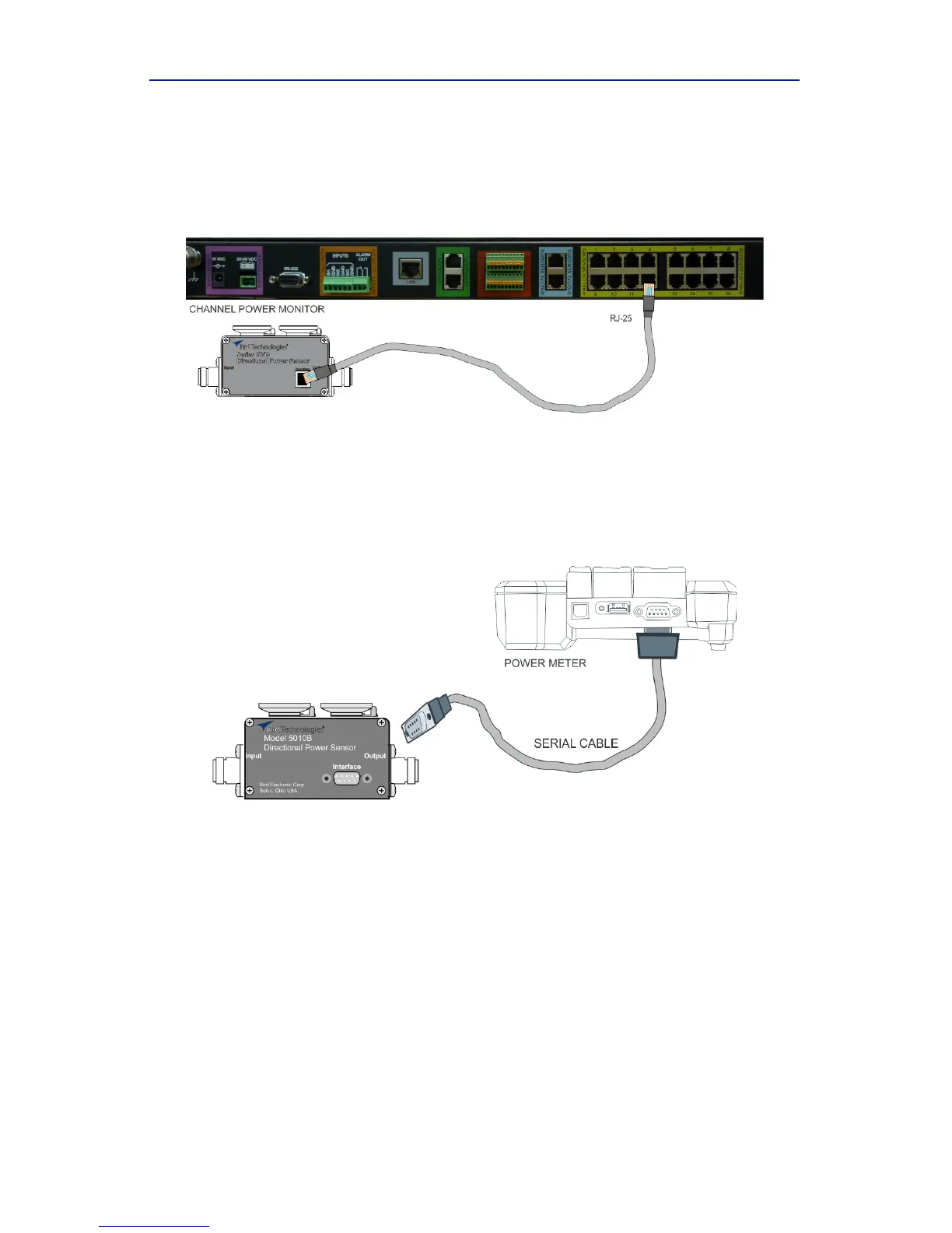
ConnectoneendofdatacabletotheRJ‐25connectoronthe5009.
Connecttheotherendofth
edatacabletooneofthechannel
inputconnectorsonaBirdChannelPowerMonitor.
Figure 1 5009 Cable Connection
b. Toconnecta5010Bor5010TDPS:
ConnecttheDP
Stothe“Sensor”serialportontheBirdDigital
PowerMeterusingthesensorcableprovided.
Figure 2 5010 Cable Connection
c. Toconnecta5014DPS:
Note: Therearecur
rentlythreeconnectionoptionsforthe5014
DPS.
ConnecttheDP
StoaUSBportonaPCusingthesensorcablepro‐
vided.UseVPM
3softwaretocommunicatewiththeDPS.
ConnecttheDP
Stothe“Sensor”USBportonaBirdDigitalPower
Meterusingthesensorcableprovided.
ConnecttheDPStoanAndr
oiddeviceusinganOTGcableandUSB
Cable.UsetheBirdRFMeterApptocommunicatewiththeDPS.