Installation
7
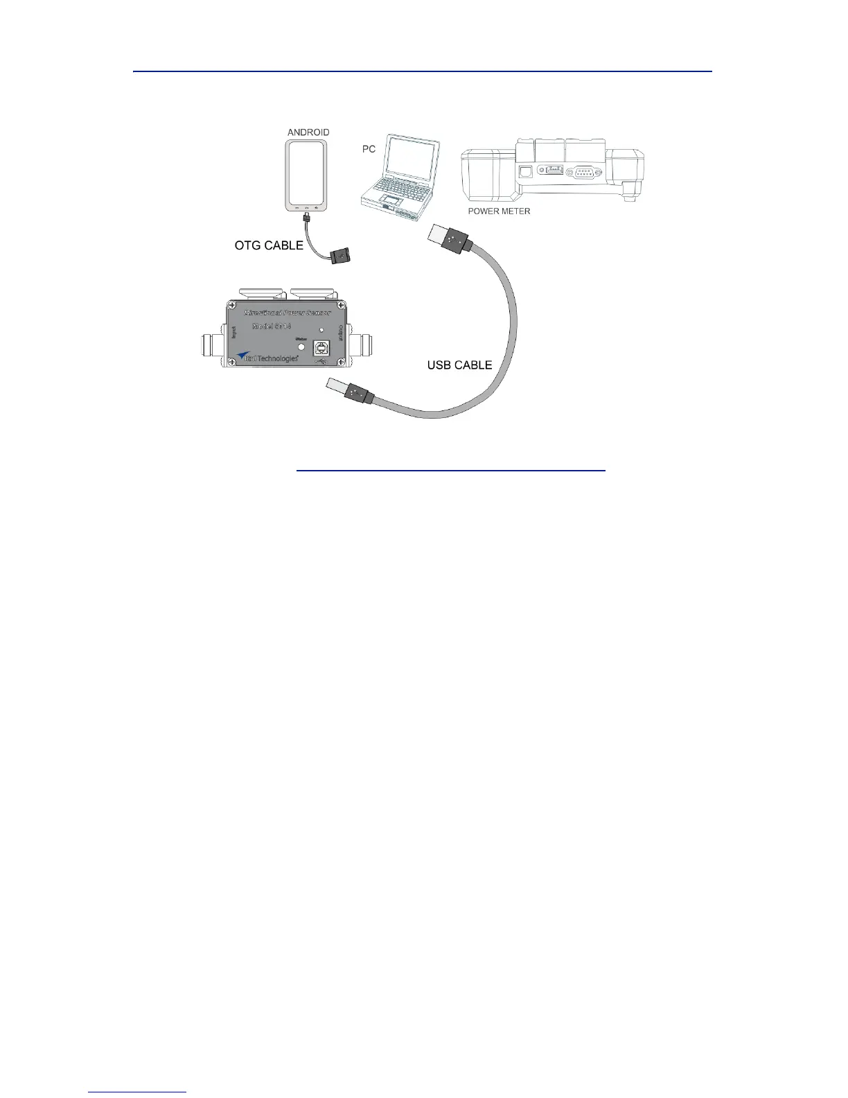
Figure 3 5014 Cable Connections
2. Con necttheRFlinetotheDPSsothatthearrowonthesensorpoints
towardstheload,
see"ElementOr ie ntat i on "onpage 2
.
Note: Thear
rowontheforwardelementshouldpointtowards
theload.
Note: Thearrowonthereflectedelementshouldpointtowards
thesource.
Note: BothelementsmustbeeitherAPM/DPMor43types,do
notmixelements.
3. RefertoDPM
/VPM3/CPMmanualsforsetupparametersforthedesired
measurement.
Note: Us
etheforwardelement’spowerratingwhensettingup
thedevice.