2
4. Mount the Height Adjustment Mechanism (O) using the 3/8” x 6 1/2” Hex Bolts (N) and the 3/8” Lock
Nuts (M) on each end of the mechanism. Tighten so there is no side to side movement possible but the
unit pivots freely. Make sure the opening of the black release box is facing downward as shown.
See Figure C.
5. Mount the entire QWIK-CHANGE assembly to the 4” Square Pole (R) using the U-bolts (A), 1/2” Flat
Washers (B), 1/2” Lock Washers (C) and 1/2” Hex Nuts (D). Position the bottom of Rim/Pole Mounting
Plate (F) at 95" above the playing surface for 7 1/2' thru 10' adjustment. Placement below this point is not
advisable as it seriously increases the chance of injury to young players. Make sure the Bison label is on
the lower Extension Channel (E). See Figure C.
6. Lower unit to bottom position for easy access to mount Backboard Supports (G) & (H), Backboard (T)
and Rim (U).
7. Mount the Upper Backboard Supports (G) and Lower Backboard Supports (H) to the Rim/Pole Mounting
End Plates (F) using the 5/16” x 1” Hex Bolts (W), 5/16” Flat Washers (Q) and 5/16” Flange Nuts (X).
Do not tighten at this time. See Figure E.
Note:
If your warning label becomes damaged or lost, call the manufacture for a replacement.
Warning!
Allow the concrete to cure for 48 hours minimum before completing installation.
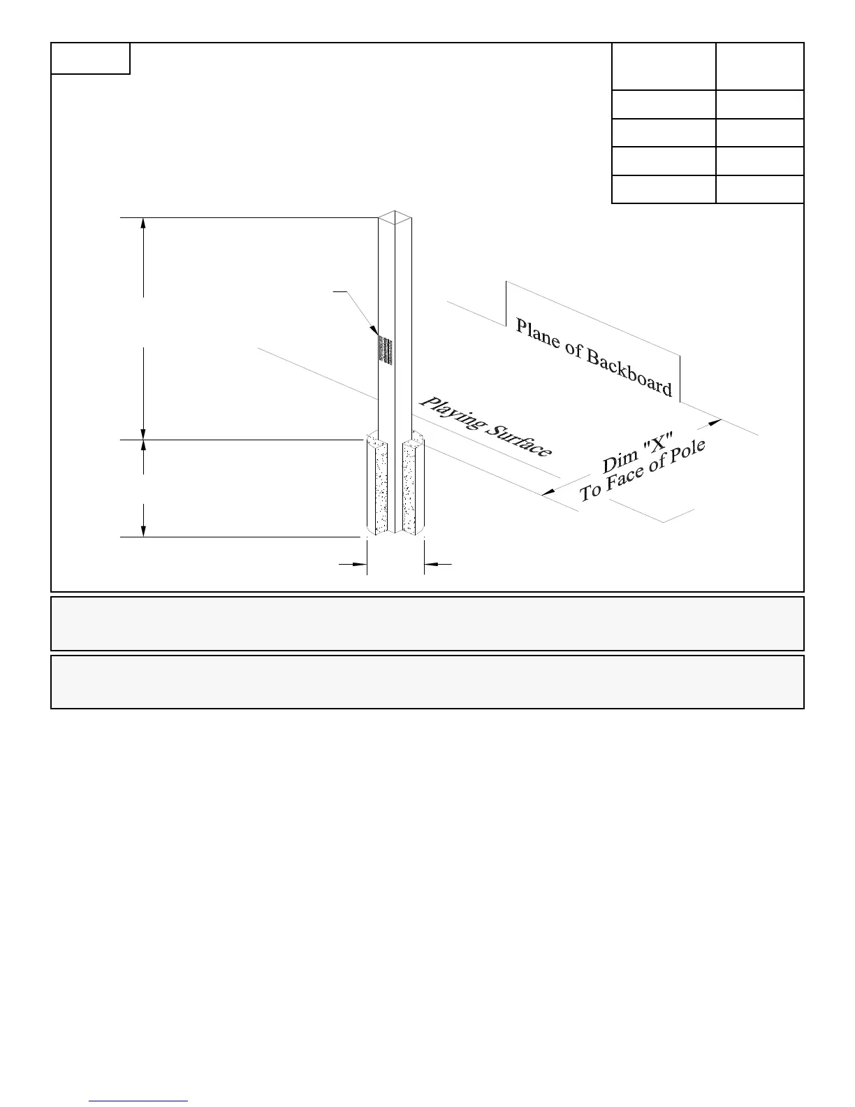
30" Reference
8" Minimum
110" Minimum
Warning Label
RIM
HEIGHT
DIM “X”
10’ 22.5”
9’ 30”
8’ 31”
7 1/2’ 28”
Figure A