3
8. Loosely attach the Backboard Mounting Angles (I) to the Backboard Supports (G) & (H) as shown with
5/16” x 1” Hex Bolts (W) and 5/16” Flange Nuts (X). Do not tighten at this time. See Figure E.
TO RAISE GOAL: Place the end of a suitable lifting pole (I.E. broom handle) under the rim or backboard
and push upward until desired height is reached. The mechanism will automatically lock in one of the fixed
adjustment positions as unit is lowered slightly.
TO LOWER GOAL: Place pole into the black release cup of the adjustment mechanism, push upward to
release, then lower the goal to the bottom most position. The mechanism will not lock at intermediate positions
on the way down as long as the cup is depressed. QWIK-CHANGE is designed to adjust from 7 1/2’ to 10’ in
6” increments.
9. Mount Backboard (T) and Rim (U) to previously assembled structure with the hardware provided with
the Rim (U). Bolts should pass through the Rim (U), then Backboard (T) and then the Rim/Pole Mounting
End Plate (F). Tighten when both Rim (U) and Backboard (T) are level.
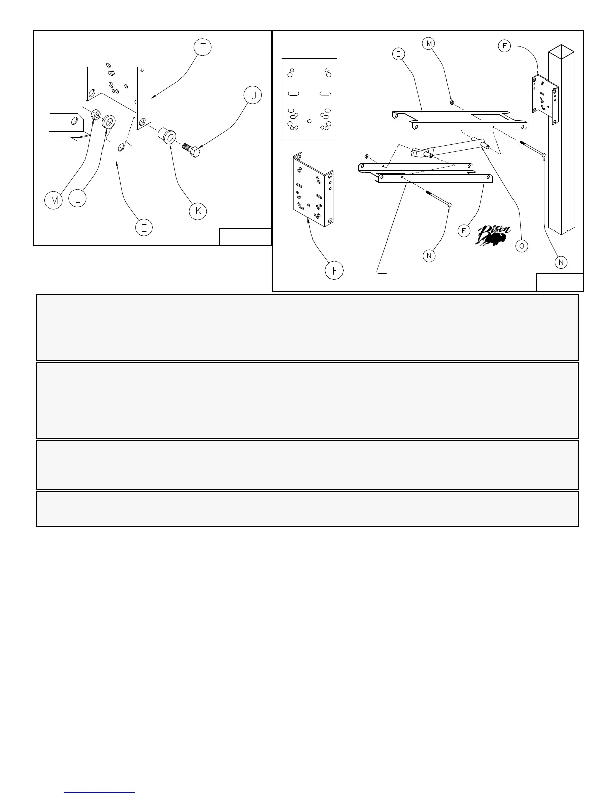
Warning!
Improper installation, maintenance or use may cause product failure or serious personal injury.
Failure to seat Pivot Bushing (K) shoulder against the outside of Rim/Pole Mounting Channels (F)
will result in poor rigidity and possible injury caused by premature wear on pivot bolts and steel parts.
Warning!
Placement of Qwik-Change below the 95” shown in Figure D is not advisable as it seriously increases
the chance of injury to young players.
Note:
Lower Backboard Supports (H) are for use with Acrylic Backboards Only.
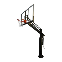
Note:
When extension arm assembly is completely assembled, the mechanism is going to want to collapse.
This is normal, as the unit requires the weight of the backboard and rim to set the mechanism into the
locked position at each setting. Use caution to avoid pinch points when proceeding with mounting the
assembly to the pole and while mounting the backboard and rim.
This end up!
Bison logo here!
Figure C
Figure B