36
ASSEMBLY
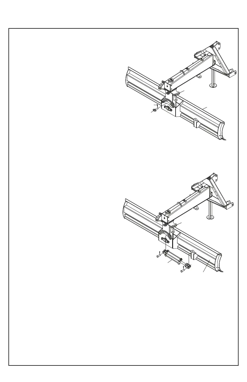
Tilt pin installation
Insert the pin and tilt angle (12) using various combina-
tions of holes between the moldboard (1) and the
turntable holes (3). Secure the angle and tilt pin (12)
with "R" lock (33).
1. Moldboard
3. Turntable
12. Tilt and angle pin
33. Lock "R"
JOIN THE TILT CYLINDER KIT TO THE REAR
BLADE (KHCN105)
1. Assemble the tilt cylinder (37) to the turntable (3)
using pin and cotter of the tilt cylinder (37), likewise join
the other end of the tilt cylinder (37) to the moldboard
(1).
1. Moldboard
3. Turntable
33. Lock "R”
37. Tilt Cylinder
3
3
1
33
12
NB80-032
NB80-033
1
37