40
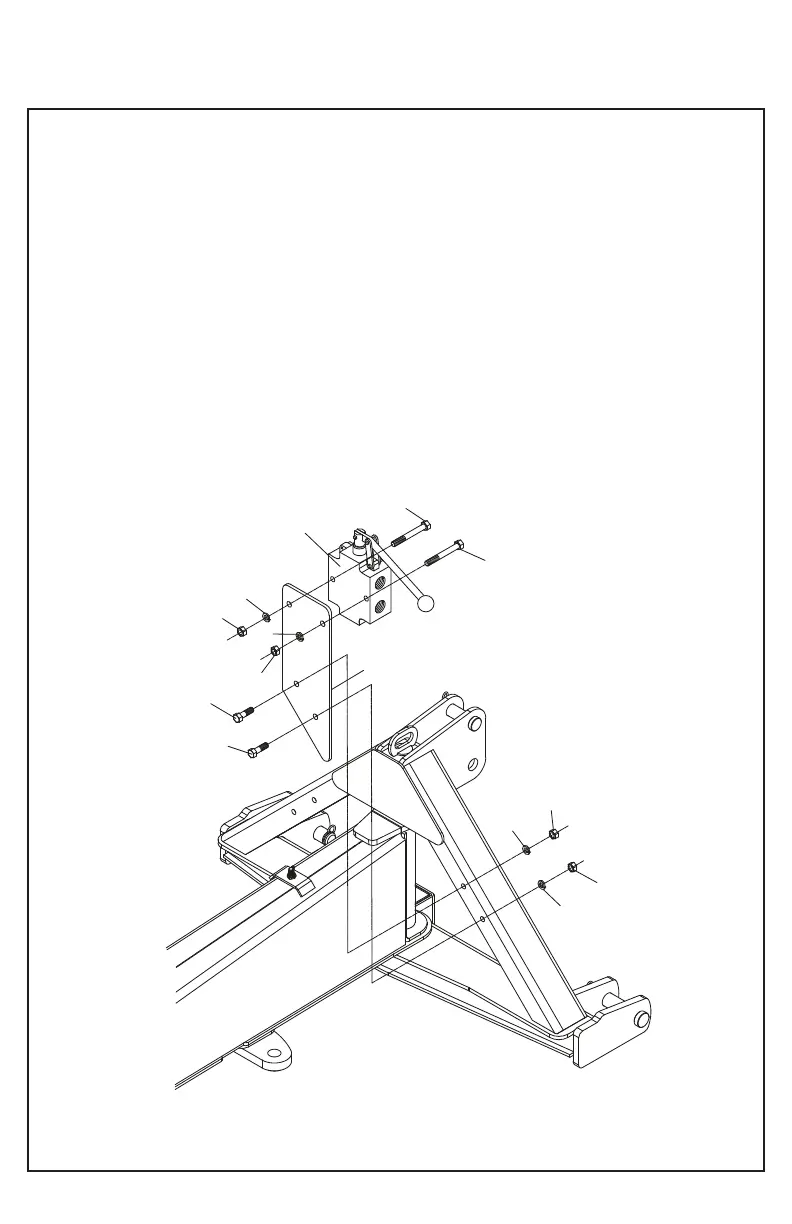
A. Insert the two screws (4) through the selector valve
(1) and the valve holder of the selector valve (2) as
shown in the drawing and securely fasten with two hex
nuts (5) and two lock washers (6).
B. Fit latch assembly to the frame as shown using two
screws (3), two hex nuts (5) and two lock washers (6).
1. Selector Valve
2. Valve Holder
3. Screw hex. 3/8 x 1 1/4 - 16 UNC G5
4. Screw hex. 3/8 x 3 - 16 UNC G5
5. Nut hex. 3/8
6. Lock washer, 3/8
SELECTOR VALVE ASSEMBLY
C6300051 (OPTIONAL)
6
5
5
6
3
3
5
5
6
6
1
4
4
2
NB80-037