KB-206-112
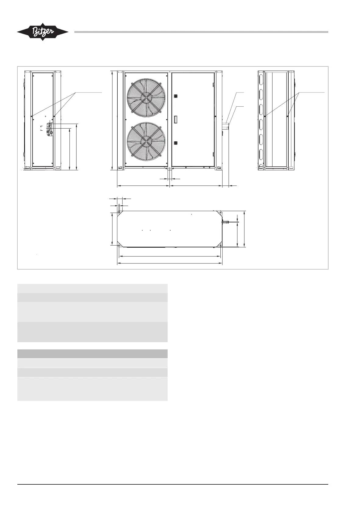
6.5 Connections and dimensional drawing
1
ØB
ØA
Y
X
648 80648
46
63
12
C
403
305
450
4
4
11
M8x30 (max.)
11
M8x30 (max.)
1253
1300
Fig.10: Connection positions (example shows LHL5E/4FES-3Y .. LHL5E/4CES-6Y)
Type ØA ØB C X Y
mm mm mm mm mm
LHL3E/2EES-2Y ..
LHL3E/2CES-3Y
22 12 830 520 575
LHL5E/4FES-3Y ..
LHL5E/4CES-6Y
28 16 1230 520 575
Connection positions
1 Refrigerant inlet (suction gas line)
4 Refrigerant outlet (liquid line)
11 Load suspension points (maximum screw-in
thread length of the screws and the screw-in
eyes: 30 mm)
Tab.4: Connection positions