EasyManua.ls Logo

Bitzer SE-C1

Bitzer SE-C1
24 pages
To Next Page IconTo Next Page
Loading...
Schutzgeräte
SE-C1 und SE-C2
für Schraubenverdichter
Inhalt
1 SE-C1 und SE-C2
2 Überwachungsfunktionen
3 Funktions- und Störmeldungen
4 Technische Daten
5 Prinzipschaltbilder
1 SE-C1 und SE-C2
Diese optionalen Schutzgeräte über-
wachen mehrere Betriebs-Parameter
und schützen so den Verdichter über
die allgemein üblichen Kontrollfunkti-
onen hinaus.
Zusätzlich zu den Funktionen des
Standard-Schutzgeräts SE-E1 (Über-
wachung von Motor- und Druckgas-
Temperatur, Drehrichtung und Pha-
senausfall vgl. ST-120) überwachen
SE-C1 und SE-C2 noch die Phasen-
symetrie, Schalthäufigkeit und Ölver-
sorgung. Sie ersetzen die Schutzgerä-
te SE-E1, INT389R sowie OFC bei
HS- und OS-Schrauben.
Das SE-C1 ist für die CSH- und die
HS.64/74-Schrauben und das SE-C2
speziell für HS.85-Verdichter konzi-
piert.
Die Schutzgeräte arbeiten über einen
großen Spannungsbereich. Dies er-
laubt den Einsatz in nahezu allen
Stromnetzen (50 und 60 Hz) sowie
eine Überwachung von Verdichtern im
Frequenzumrichter-Betrieb. Ein Vor-
schaltgerät für den Betrieb von Son-
dermotoren für 575 und 690 V ist
nicht erforderlich.
Protection Devices
SE-C1 and SE-C2
for Screw Compressors
Content
1 SE-C1 and SE-C2
2 Monitoring functions
3 Functional and failure messages
4 Technical data
5 Schematic wiring diagrams
1 SE-C1 and SE-C2
These optional protection devices
monitor several operational parame-
ters to protect the compressor beyond
the standard control functions.
SE-C1 and SE-C2 offer all functionali-
ty provided by the standard protection
device SE-E1 (monitoring of motor
and discharge gas temperatures, rota-
tion direction and phase failure, see
ST-120), but also monitor phase sym-
metry, switching frequencies and oil
supply. They replace the protection
devices SE-E1, INT389R and OFC for
HS and OS screws.
The SE-C1 is designed for CSH and
HS.64/74 screws, the SE-C2 especial-
ly for the HS.85 compressors.
The protection devices work over a
large voltage range. This allows the
use in nearly all power supply sys-
tems (50 and 60 Hz), as well as for
monitoring compressors with frequen-
cy inverters. A step down resistor
device for the operation of special
motors for 575 and 690 V is not
required.
Dispositifs de protection
SE-C1 et SE-C2
pour les compresseurs à vis
Sommaire
1 SE-C1 et SE-C2
2 Fonctions de contrôle
3 Fonctions et pannes signalées
4 Caractéristiques techniques
5 Schémas de principe
1 SE-C1 et SE-C2
Ces dispositifs de protection optionnaux
contrôlent plusieurs paramètres de fonc-
tionnement et protègent aussi le com-
presseur au-delà des fonctions de contrô-
le usuelles.
En plus des fonctions du dispositif de pro-
tection standard SE-E1 (contrôle de la
température moteur et du gaz de refoule-
ment, sens de rotation et défaut de
phase, voir ST-120) sont supplémentés
par des fonctions des SE-C1et SE-C2:
surveillance de la symétrie des phases,
de la fréquence d'enclenchement et d'ali-
mentation en huile. Ils remplacent les dis-
positifs de protection SE-E1, INT389R et
OFC pour des vis HS et OS.
Le SE-C1 a été conçu pour les vis CSH
et HS.64/74, le SE-C2 spécialement pour
les compresseurs HS.85.
Les dispositifs de protection couvrent une
large plage de tensions. Ils sont donc uti-
lisables sur pratiquement tous les
réseaux électriques (50 et 60 Hz) ainsi
que pour le contrôle des compresseurs
avec convertisseur de fréquences. Un
transformateur pour le fonctionnement
des moteurs spéciaux pour 575 et 690 V
n'est pas nécessaire.
ST-121-2
Technische Information
Technical Information
Information Technique
Question and Answer IconNeed help?

Do you have a question about the Bitzer SE-C1 and is the answer not in the manual?

Bitzer SE-C1 Specifications

General IconGeneral
BrandBitzer
ModelSE-C1
CategoryMeasuring Instruments
LanguageEnglish

Summary

SE-C1 and SE-C2 Protection Devices

Monitoring Functions

Temperature Monitoring

Monitors motor and discharge gas temperatures for protection.

PTC Measuring Circuit Monitoring

Monitors PTC circuit for shorts or cable failure.

Phase Failure, Asymmetry, and Rotation Direction Monitoring

Monitors phase sequence, failures, and asymmetry for safety.

Maximum Switching Frequency Monitoring

Limits compressor start frequency to prevent overload.

Oil Level Monitoring

Monitors oil level status and triggers shutdown if low.

Oil Supply Monitoring

Monitors oil flow to ensure adequate lubrication.

Oil Stop Valve Monitoring

Monitors the oil stop valve for proper function.

Manual Reset Procedure

Details the steps for manually resetting the protection device.

Terminal Box Connections

SE-C1 Terminal Box Electrical Connection

Shows electrical connections for SE-C1 in CSH and HS.64/74 compressors.

SE-C2 Terminal Box Electrical Connection

Shows electrical connections for SE-C2 in HS.85 compressors.

Functional and Failure Messages

Signal Lamp H1 Off, H2 On

Indicates pause time or restricted switching frequency.

Signal Lamp H1 On, H2 On

Indicates phase issues like wrong rotation, failure, or asymmetry.

LED Indicators on Protection Device

Explains the meaning of the four LEDs on the protection device.

Signal Output at Protection Device

Specifies terminals for signal outputs H1 and H2.

Technical Data and Diagrams

Technical Data Specifications

Lists operating voltage, motor voltage, relay, and PTC circuit data.

Dimensional Drawing

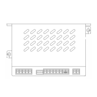
Provides physical dimensions and layout of the device.

Schematic Wiring Diagrams

Presents simplified circuit diagrams for components and functions.

CSH Compressor Operation Modes

CSH: Part Winding Start Infinite Capacity Control

Details part winding start with infinite capacity control for CSH.

CSH: Part Winding Start 4-Step Capacity Control

Details part winding start with 4-step capacity control for CSH.

CSH: Star-Delta Start Infinite Capacity Control

Details star-delta start with infinite capacity control for CSH.

CSH: Star-Delta Start 4-Stage Capacity Regulation

Details star-delta start with 4-stage capacity regulation for CSH.

HS Compressor Operation Modes

HS.64 & HS.74: Frequency Inverter Operation

Shows frequency inverter operation for HS.64 & HS.74 compressors.

HS.85: Part Winding Start Infinite Capacity Control

Details part winding start with infinite capacity control for HS.85.

HS.85: Part Winding Start 4-Step Capacity Control

Details part winding start with 4-step capacity control for HS.85.

Frequency Inverter Operation

SE-C1 and CSH with Frequency Inverter

Wiring diagram for SE-C1 with CSH compressors and frequency inverter.

SE-C1 and HS.64 & HS.74 with Frequency Inverter

Wiring diagram for SE-C1 with HS.64 & HS.74 and frequency inverter.

SE-C2 and HS.85 with Frequency Inverter

Wiring diagram for SE-C2 with HS.85 and frequency inverter.

Related product manuals