◈ Information
This Installation Guide includes a brief outline of information necessary for product
installation. For more detailed installation information, please refer to the user manual in the
enclosed CD. The contents of the CD include the following.
1. Manual: User Manual, Code Chart, and Control Commands
2. Drivers: Windows Driver, OPOS Driver
3. Utility: Logo Download Tool
We at Bixolon Co., Ltd. constantly strive to improve product functions and quality. To do
this, the specifications of our product and the contents of the manual may change without
prior notice.
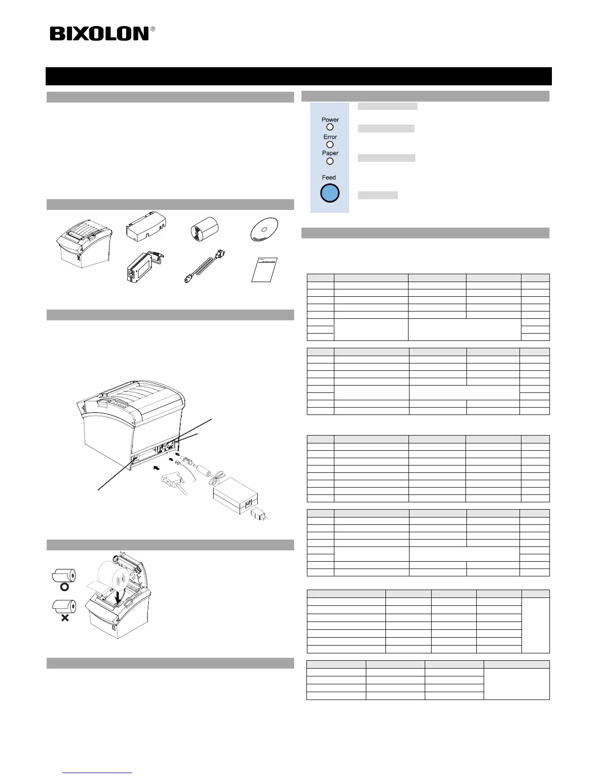
◈ Components
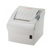
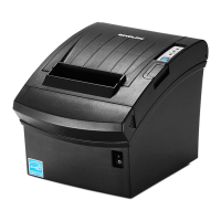
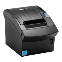
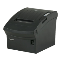
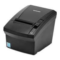
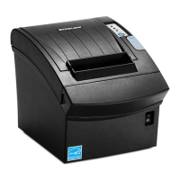
SRP-350/352III
Cable Cover
Paper Roll
Procuct Installation CDProcuct Installation CD
CD
AC/DC Adaptor
Power Cord
Installation Guide
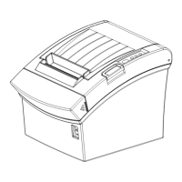
◈ Cable Connection
1. Turn off the printer and the host ECR (host computer).
2. Plug the power cord into the adaptor and then plug the adaptor into the power connector of
the printer.
3. Check the interface type on the back of the printer (Serial, Parallel, USB or Ethernet), and
connect the interface connector cable.
4. Plug the drawer kick-out cable into the drawer kick-out connector on the printer.
※ Do not use an adapter that was not supplied with the printer.
◈ Installing Paper Roll
1. Open the Cover-Open button to open the cover.
2. Insert a new paper roll in the right direction.
3. Pull out a small amount of paper and then close
the cover.
※ Note
To make the paper tightly close to the roller when
closing the cover, press the center of the cover.
Printing quality may not be optimum if
recommended paper is not used.
(Refer to the User's Manual.)
◈ Paper Jam (Refer to 1-6 in User Manual)
1. Turn the power of the printer off or on and open the cover to remove the paper.
2. If the cover is not opened, turn off the power of the printer and separate the cover-cutter
and then turn the knob of the auto cutter to open the cover.
◈ Using Control Panel
• Power (Signal Lamp)
When turning on the power, a green LED will be lit.
• Error (Signal Lamp)
When an error occurs, a red LED will be lit.
(e.g. no paper, cover ajar, etc.)
• Paper (Signal Lamp)
Red LED will be lit when the paper roll is running low. The LED
blinks when the printer is in self-test standby mode or macro execution
standby mode.
• Feed (Button)
Press the FEED button once to discharge extra paper. Holding down
the FEED button will discharge paper continuously until the button is
released.
◈ Setting DIP Switches
To change the Dip Switches settings, turn the printer power off. Any changes while the
printer is on will not be processed.
1. Serial Interface Setting
• DIP Switch 1
SW Function ON OFF Default
1-1 Auto Line Feed Enabled Disabled OFF
1-2 Flow Control XON/XOFF DTR/DSR OFF
1-3 Data Length 7-bit 8-bit OFF
1-4 Parity Check Yes No OFF
1-5 Parity Selection EVEN ODD OFF
1-6
Baud Rate Selection (bps) Refer to the following Table 1
OFF
1-7 ON
1-8 OFF
• DIP Switch 2
SW Function ON OFF Default
2-1 Reserved - - OFF
2-2 Reserved - - OFF
2-3 Internal Bell Control Disabled Enabled OFF
2-4 Auto Cutter Selection Disabled Enabled OFF
2-5
Printing Density Refer to the following Table 2
OFF
2-6 OFF
2-7 Near End Sensor Contorl Disabled Enabled OFF
2-8 Auto External Buzz Enabled Disabled OFF
2. Parallel / USB / Ethernet Interface Setting
• DIP Switch 1
SW Function ON OFF Default
1-1 Auto Line Feed Enabled Disabled OFF
1-2 Reserved - - OFF
1-3 Reserved - - OFF
1-4 Reserved - - OFF
1-5 Reserved - - OFF
1-6 Reserved - - OFF
1-7 Reserved - - ON
1-8 Reserved - - OFF
• DIP Switch 2
SW Function ON OFF Default
2-1 Reserved - - OFF
2-2 Reserved - - OFF
2-3 Internal Bell Control Disabled Enabled OFF
2-4 Auto Cutter Selection Disabled Enabled OFF
2-5
Printing Density Refer to the following Table 2
OFF
2-6 OFF
2-7 Near End Sensor Contorl Disabled Enabled OFF
2-8 Auto External Buzz Enabled Disabled OFF
• Tab. 1 – Selection of Baud Rate (bps)
Transmission Speed 1-6 1-7 1-8 Default
2400 ON OFF OFF
9600
4800 ON OFF ON
9600 OFF ON OFF
19200 OFF OFF OFF
38400 OFF ON ON
57600 OFF OFF ON
115200 ON ON ON
• Tab. 2 – Selection of Printing Density
Printing Density 2-5 2-6 Default
Level 1 OFF OFF
- Level 1 is Default
- Level 4 is Darkest
Level 2 ON OFF
Level 3 OFF ON
Level 4 ON ON
Printer Installation Guide
THERMAL PRINTER SRP-350/352III
Power
cord
Drawer
kick-out
cable
Interface cable
(Serial/Parallel/USB/Ethernet)
Adaptor
Drawer kick-out connector
Power connector
Interface connector
 Loading...