11
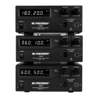
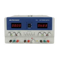
16. Slave Voltage Indicator Display in full 3-digits Green 0.56” LED.
17. Slave Current Indicator Display in full 3-digits Red 0.56” LED.
18. Voltage Adjustment knob for adjusting Slave output voltage when master power is at
C.V. Mode.
19. Current Adjustment knob for adjusting Slave output current when master power is at
C.C. Mode.
20. Negative output terminal of the Slave 0-32V/0-3A Output (black).
21. Ground terminal of the Slave output (green).
22. Positive output terminal of the Slave 0-32V/0-3A Output (Red).
23. C.C. Mode LED (Red) for the Slave to indicate constant current.
24. C.V. Mode LED (Green) for the Master to indicate constant voltage.
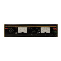
8.3 REAR PANEL DESCRIPTION
Refer to the Rear panel drawings and the numbers assigned to various
objects on the front panel. (see page 12)
25. Heat sink for dissipating the heat of power devices.
26. Fan Ventilation (80mm 12V DC Fan).
27. Power input socket
28. Fuse holder and input line selector.
29. The input Line voltage indicator. (Refer to mark)
∇