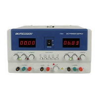
GENERAL CONTROLS AND INDICATORS
1. POWER Switch. Turns power on and off.
2. TRACKING Mode Switches. Two pushbutton switches that
select INDEPendent mode, SERies tracking mode, or PARallel
tracking mode as follows:
a. When INDEP/TRACK switch is disengaged (out),
the unit is in the INDEPendent mode and the “A” and “B”
power supplies are completely independent from one
another.
b. When the INDEP/TRACK switch is engaged (in)
and the SER/PAR switch is disengaged (out), the unit is in
the TRACKing SERies mode. In this mode, maximum
voltage of both supplies is set using the “A” VOLTAGE
controls (voltage at output terminals of the “B” supply
tracks the voltage at the output terminals of the “A” supply).
Also, in this mode of operation the positive terminal (red) of
the “B” supply is internally connected to the negative
terminal (black) of the “A” supply. This allows the two
supplies to be used as one 0-to-60 volt supply.
c. When both INDEP/TRACK and SER/PAR
switches are engaged (in), the unit is in the TRACKing
PARallel mode. In this mode the “A” and “B” supplies are
wired together in parallel and both the maximum current
and voltage are set using the “A” controls. The “A” and “B”
outputs can be used as two individual (but tracking) power
supplies or just the “A” output can be used as a 0-to-30 volt
supply with a 4 A capability.
3. 0-30V/4-6.5V Switch. Controls “A”/4-6.5V LED
Display. When this switch is in the 0-30V position
(out), the LED display monitors the “A” (0-30 V)
supply. When this switch is in the 4-6.5V position
(in), the LED display monitors the 4-6.5V supply.
4. Right V/A Switch. Selects current or voltage metering
mode for the “A” 0-30 V supply or the 4-6.5 V supply
(depending on setting of 0-30 V/4-6.5 V switch). When
in the A (amps) position (in), current is read from the
“A”/4-6.5 V LED Display. When in the V (volts)
position (out), voltage is read from the “A”/ 4-6.5 V
LED Display.
5. “A”/4-6.5 V LED Display. Digital display indicates
voltage or current at the 0-30 V “A” supply or the 4-6.5
V supply (depending on the setting of the Right V/A and
0-30 V/4-6.5 V switches).
4-6.5 V SUPPLY CONTROLS AND INDICATORS
6. “-” Terminal (Black). Negative polarity output terminal
for 4-6.5V supply.
7. “+” Terminal (Red). Positive polarity output terminal
for 4-6.5V supply.
8. Voltage Level Control. Adjusts output voltage for 4-
6.5V supply. Fully counterclockwise rotation adjusts
output voltage to 4V. Clockwise rotation increases
voltage to a maximum of 6.5V (full clockwise rotation).
9. 5 A OVERload Indicator. Lights when load on 4-6.5
Volt supply becomes too large.