Do you have a question about the BK Radio KNG-P150 and is the answer not in the manual?
Provides an overview of the BK Radio KNG Series APCO Project 25 portable digital radios.
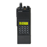
Details the KNG as a handheld FM transceiver designed for Land Mobile services, supporting analog and digital modes.
Lists operational features, channel capacity, operating voltage, physical dimensions, channel spacing, and antenna type.
Lists factory-installed options available at the time of printing, such as Intrinsically Safe and OTAR.
Recommends using only BK Radio approved accessories and provides a web link for accessory lists.
States that equipment must be licensed by the FCC and offers dealer assistance for applications.
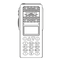
Identifies and describes the physical controls on the radio, including top and side panel buttons.
Identifies and describes external controls and indicators on the radio.
Explains the KNG display's programmability for various options and functionality.
Explains the meaning of various icons and symbols on the LCD display, such as signal strength and battery level.
Describes programmable information lines for conventional and trunked channels.
Details how switches and buttons can be programmed for different functions via PC programming.
Lists available functions that can be assigned to buttons and menu items for conventional channels.
Provides contact information for local BK Radio dealers and BK Radio Attention: Customer Service.
Introduces the section containing information on installation and programming of BK Radio KNG radios.
Covers fundamental operation procedures like powering on, receiving, and transmitting signals.
Explains how to receive signals, adjust volume, and interpret the display indications.
Details the process of transmitting, including PTT usage and indicator lights.
Identifies and describes the physical controls on the radio, including buttons and switches.
Lists functions assignable to buttons and menu items, differentiating trunking and conventional.
Explains how to navigate and select options using the keypad menu for programming functions.
Describes various methods for selecting channels and zones, including knob, button, menu, and keypad entry.
Details options for using the channel knob and keypad for direct channel or zone entry.
Explains programmable display options for three channel information lines.
Explains how to create and manage command zones for channels by adding channels from standard operating zones.
Details conventional channel code guard receive/transmit and APCO Project 25 digital NACs.
Explains the use of CTCSS/CDCSS for selective calling and carrier squelch operation.
Covers Network Access Codes (NACs) and Talk Group IDs (TGIDs) for digital systems' selective squelch.
Describes the receiver and transmitter's capability to operate in analog and digital modes independently.
Explains how mixed mode talkback transmits in the same mode as the received signal when hold time is active.
Covers system registration and transmitting procedures for radios with optional P25 Trunking capability.
Details conventional channel scan features, operation, and scan list designation.
Explains how users can add or remove channels from the scan list using buttons or menu items.
Describes how talkback scan operates when PTT is pressed during scan delay time.
Explains vote scan functionality for multicast conventional systems, allowing selection of best signal.
Covers the ability to scan trunking and conventional channels simultaneously via a dual mode scan list.
Explains how enhanced scan combines priority and channel scan into a single operation.
Details how priority channels are monitored for incoming traffic and how the radio switches channels.
Describes how priority channels can be selected system-wide or zone-specific and changed via keypad.
Explains how zone scan operates when Zone Scan and Channel Scan are active, scanning designated zones.
Describes how users can add or remove zones from the zone scan list using buttons or menu items.
Explains the ability to select and assign pick list functions like code guards and NACs to specific channels.
Details selecting CTCSS/CDCSS code guards from the pick list for analog or mixed mode channels.
Explains selecting Network Access Codes (NACs) from the pick list for digital or mixed mode channels.
Describes selecting Talk Group IDs from the pick list for conventional digital channels.
Covers selecting encryption keys for digital or mixed mode channels that do not have key lock programmed.
Explains selecting encryption keysets from the pick list for OTAR equipped radios.
Details individual unit calls for conventional digital and trunking channels using P25 Unit IDs.
Explains P25 Emergency Operation for digital channels using P25 protocol or analog channels using MDC protocol.
Details secure communication configuration, basic operation, and display indicators for encryption.
Explains how to program selectable encryption for channels using a switch, button, or menu item.
Describes selecting encryption keys for channels from the radio's key pick list.
Covers selecting encryption keysets from the pick list for OTAR radios to use encryption keys.
Explains how to manually request an encryption rekey from the Key Management Facility (KMF).
Details how to view and select active encryption keysets, limited to 8 keysets, 64 keys each.
Describes the method to panic-zeroize all encryption keys, including OTAR and Tactical OTAR keys.
Covers sending and receiving text messages and radio status messages on digital P25 channels.
Explains sending predefined, manually entered, or locally stored text messages via the TXT button or menu.
Details how to store manually entered text messages in the 'Manual Entry List' menu.
Explains transmitting enumerations corresponding to predefined messages stored in other radios.
Covers sending status updates to other radios by selecting programmed messages.
Describes selecting message type for unit, group, or dispatch calls from the 'Select Target Type' menu.
Explains selecting target radios for unit calls: last call, call list, or entering unit ID.
Details sending status messages to groups based on matching Talk Group ID, manually or from a pick list.
Explains sending status messages to a dispatch console.
Covers receiving two-tone, DTMF, MDC1200 pages and sending/receiving call alerts on digital channels.
Explains receiving pages on analog channels with voice mute activated by the radio's icon.
Details sending and receiving call alert messages on digital channels, including target radio selection.
Explains checking the availability of a KNG radio with a specific P25 ID via radio check request.
Describes temporarily disabling other radios using unit ID number and re-enabling with an Uninhibit command.
Covers various additional radio functions such as backlight, battery life, and busy channel operation.
Explains assigning backlight on/off control to a switch, button, or menu item.
Details information provided on battery life status, including percentage capacity and estimated time.
Explains different radio reactions to a busy channel: Off, Indicate, Lockout, Override, and Automatic.
Describes how channel selection can be assigned to a button or menu item for accessing channels.
Explains setting up radios by sending or receiving programmed information via a cloning cable.
Describes adjusting the screen contrast using the +/- buttons and pressing ENTER to set.
Explains the variety of control lock options, including Lock Keypad Only and Lock All Controls.
Describes displaying and editing the radio's date and time, which stays stored when powered off.
Explains accessing and sending GPS coordinates based on triggers like PTT, periodic, emergency, or power on/off.
Details turning the radio completely off using the Hard Power Down function.
Describes returning the radio to a preprogrammed channel configured in the PC Radio Editor.
Explains how radio information, including channel, zone, and global parameters, can be edited using the keypad.
Describes setting the minimum audible volume level through the customizable setting in PC Radio Editor.
Explains the three available settings (Off, On, Open) for monitoring traffic on a selected channel.
Describes temporarily removing a nuisance channel from the scan list by pressing the assigned button.
Explains using the phone function to dial numbers and the Hang Up button to end calls.
Describes transmitting a preprogrammed DTMF tone sequence when the RAT button is pressed and held.
Explains how to view radio information like UID, IP, OTAR registration, and uptime via the 'Radio Info' menu.
Explains transmitting on the receive frequency of the selected channel when T/A is enabled, indicated by an icon.
Describes transmitting a programmed duration 781.3Hz tone when pressed and held.
Explains activating a long-press signal equivalent to emergency alarm, requiring ANI Mode set to five-tone.
Details changing the signal strength required for the speaker to unmute using the squelch menu.
Shows information for the currently operating site, including Site ID, Site Alias, and RSSI.
Explains preventing the radio from searching for other sites by locking it to the currently selected site.
Describes automatically searching and selecting the best available trunking site.
Explains disabling audible indicators and lighting functions when Surveillance Mode is on.
Covers performing various system tests when connected to appropriate test equipment.
Explains transmitting in digital or analog mode for mixed-mode channels, indicated by 'D' or 'A' annunciator.
Describes selecting transmit power between programmed high and low settings, indicated by 'H' or 'L' on LCD.
Explains selecting two-tone lists for sending the two-tone signal, programmed via PC Radio Editor.
Details viewing radio version information including date, software, DSP, file format, and PCB revision.
Explains switching between programmed channel zones via button, switch, or menu item.
Covers radio programming procedures, parameters, and access, noting trunking systems cannot be programmed via keypad.
Details using navigation buttons (diamond, arrows, square) while in programming mode.
Outlines the keypad programming sub-menus for editing global, system, zone, and channel parameters.
Explains editing programmable global settings, including display lines, user password, and system priority.
Describes programming the three main display lines (top, middle, bottom) with radio information.
Details editing programmable system settings, including system priority channels and transmit on priority 1.
Explains assigning system priority channels that are monitored during priority scan regardless of the operating zone.
Describes transmitting on the System Priority 1 channel when Priority Scan is on.
Details editing zone settings, including adding, deleting, editing zones, and zone priority.
Explains editing channel settings, including adding, deleting, and editing channel parameters.
Describes the steps to delete a channel from programmed zones by selecting it from a list.
Explains changing programmable channel information, including label, frequency, mode, and guard.
Details entering a valid receive frequency in MHz, divisible by 1.25kHz.
Describes selecting Analog, Digital, or Mixed Mode for receive operation.
Explains selecting Off, Tone, or Digital for analog/mixed mode receive channels to filter signals.
Details programming a receive NAC via keypad or selecting from a pick list for analog or mixed mode channels.
Describes selecting Normal or Selective squelch mode for digital/mixed mode receive channels.
Explains selecting Narrowband or Wideband spacing for analog or mixed mode channels.
Describes locking channels in low power, high power, or selectable transmit power modes.
Details entering a valid transmit frequency in MHz, divisible by 1.25kHz.
Describes selecting Analog, Digital, or Selectable transmit modes.
Explains selecting Off, Tone, or Digital for analog/mixed mode transmit channels.
Details programming a transmit NAC via keypad or selecting from a pick list for analog or mixed mode channels.
Describes programming a transmit Talk Group ID via keypad or pick list for analog or mixed mode channels.
Explains pre-programming and editing P25 IDs and labels for unit calls, up to 100 entries.
Details pre-programming up to 32 user-selectable CTCSS or CDCSS subaudible tones via keypad.
Explains programming up to 32 user-selectable NACs via keypad, with values in hexadecimal.
Details programming up to 32 user-selectable TGIDs via keypad, with values from 1 to 65535.
Provides a table showing characters available for input via the keypad during programming.
Introduces the section describing equipment and theory of operation, referencing schematic diagrams.
Describes the major sub-assemblies comprising the BK Radio KNG Series radio.
Details the system board's components: microprocessor, voltage regulation, audio amp, and baseband signal processor.
Describes the RF board's components: receiver circuitry, transmitter power amplifier, synthesizer, and VCOs.
Explains the functional blocks and operation of the system board, including microprocessor and PMU.
Details the core microprocessor, voltage regulators, baseband signal processor, and audio power amplifiers.
Explains the microprocessor's communication with other components and its control functions.
Describes how multiple voltage regulators provide power for circuitry located on the System Board.
Explains the signal processing algorithms for analog and digital modes implemented by the baseband processor.
Covers the PMU's support for power, clock requirements, and peripheral interfaces for the microprocessor.
Describes Class-D amplifiers used to drive internal and external speakers for audio output.
Details the RF board's functions: RF input/output, synthesizer, and transmitter sections.
Describes the harmonic filter for signal filtering and the antenna switch for routing signals.
Explains the synthesizer's circuits for frequency generation, modulation, and buffering.
Details the operation of the TCXO, synthesizer IC, loop filter, and VCOs within the synthesizer block diagram.
Explains the functions of the PA driver, PA, antenna switch, and harmonic filter in the transmitter section.
Details receiver circuits including preselector, LNA, mixer, crystal filter, and AD9864 IC.
Explains tunable preselector filters, LNA, image rejection filter, mixer, and AD9864 IC functions.
Introduces the section containing troubleshooting and assembly/disassembly procedures.
Covers visual inspection and disassembly steps for the radio, including battery and antenna removal.
Details checking external connections and internal components for damage or defects before disassembly.
Provides step-by-step instructions for removing the battery pack and antenna from the radio.
Describes how to remove press-on shields by gently prying the lid, some requiring unsoldering.
Provides instructions for cleaning the equipment case, panel, receptacles, and plugs using lint-free cloths.
Advises referring to parts lists and using approved components for repairs to avoid voiding warranty.
Provides information for performance tests, including test setups and recommended equipment.
Details connecting an RF signal generator to the radio antenna input for FM modulation testing.
Illustrates test box and transmitter test setups for performance measurements using specified equipment.
Introduces the section for identifying parts in BK Radio's KNG Portable radios.
Explains that replacement parts lists contain specific information on each part and sub-assembly.
Explains symbols used in assembly drawings to identify parts, references, and notes.
Provides a diagram showing connections between major assemblies like the System Board, RX/TX Board, and Accessory Connector.
Lists parts for the final assembly of the KNG portable radio, including chassis, knobs, and covers.
Lists parts for the front panel assembly, including case, flex circuit, connectors, tape, and buttons.
Lists parts for the systems assembly, including the main system board, microphone element, and shields.
Lists components for the system board, including various capacitors (C1-C40).
Lists various capacitor parts (C41-C64) used on the system board.
Lists diodes (D1-D25) and ferrite beads (FB1-FB16) used on the system board.
Lists various resistor parts (R1-R29) used on the system board.
Lists integrated circuits (U1-U41, U99) used on the system board, including their part numbers and descriptions.
Details connector assignments and pinouts for the systems board, including accessory and display connectors.
Lists parts for the P150 VHF assembly, including chassis, tape, coils, connectors, and shields.
Shows an exploded view and part numbers for the P150 VHF board assembly, illustrating component placement.
Lists components for the P150 VHF board, including capacitors (C1-C40).
Lists parts for the P400 UHF assembly, including chassis, tape, coils, connectors, and shields.
Shows an exploded view and part numbers for the P400 UHF board assembly, illustrating component placement.
Lists components for the P400 UHF board, including capacitors (C1-C40).
Lists parts for the P800 RF board sub-assembly, including chassis, tape, connectors, and shields.
Shows an exploded view and part numbers for the P800 RF board assembly, illustrating component placement.
Lists components for the P800 RF board, including capacitors (C1-C40).
| Brand | BK Radio |
|---|---|
| Model | KNG-P150 |
| Category | Portable Radio |
| Language | English |