7
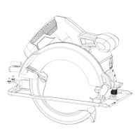
OVERVIEW (FIG. 5)
2. Main handle
3. Secondary handle
5. Saw blade
6. Saw blade lower guard
8. Saw blade spanner wrench
10. Outer blade clamp washer
11. Blade retaining bolt
12. Depth adjustment lever
13. Depth scale
15. Saw blade hex wrench
ASSEMBLY / ADJUSTMENT SET-UP
WARNING: Always unplug saw from
power supply before any of the following
operations.
Adjusting the depth of cut (fig. 6 & 7)
The depth of cut should be set according
shoe.
position. The corresponding depth of
cut can be read from the scale (13).
in place.
one tooth of the blade projects below
figure 7.
ADJUSTING THE BEVEL ANGLE (FIG. 8)
This tool can be set to bevel angles
the saw shoe.
position. The corresponding bevel
saw shoe in place.
ATTACHING THE BLADE (FIG. 9 & 10)
protrusions of the spanner wench (8)
into the holes in the outer washer (10)
Loosen and remove the blade
retaining screw (11) by turning the hex
Place the saw blade (5) onto the
the arrow on the blade points in the
same direction as the arrow on the upper
gaurd of the tool.
Fit the outer washer (10) on the spindle with
the larger flat surface against the blade.
Insert the blade retaining screw (11)
into the hole in the spindle.
6
7
Tip of tooth
Surface of wood
12
13
8
5
1
3
2
5
6
8
10
11
 Loading...