Step 2
Remove protective cover plate over power supply’s input
power terminal strip.
Step 3
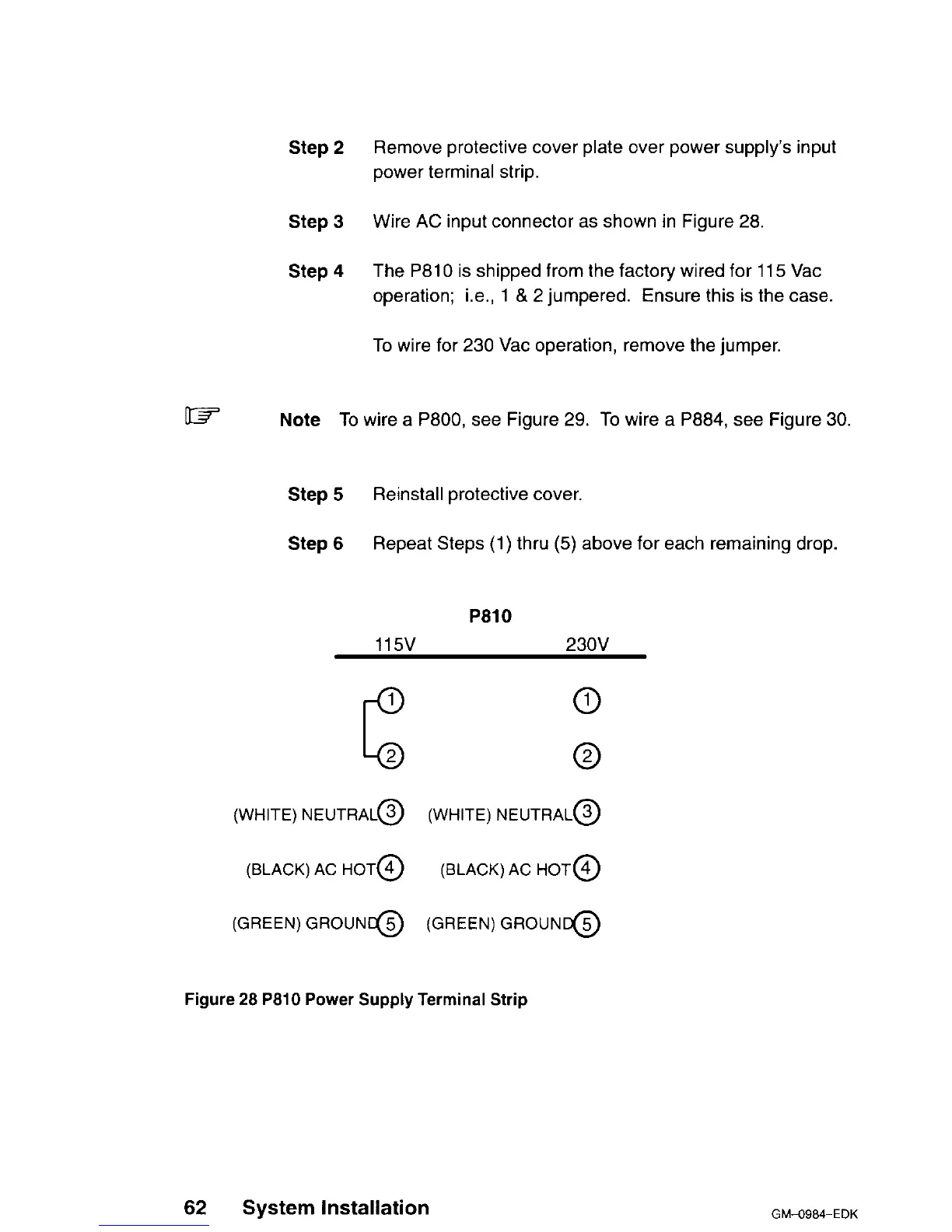
Wire AC input connector as shown in Figure 28.
Step 4
The P810 is shipped from the factory wired for
115
Vat
operation; i.e., 1 & 2 jumpered. Ensure this is the case.
To wire for 230 Vat operation, remove the jumper.
w
Note To wire a P800, see Figure 29. To wire a P884, see Figure 30.
Step 5
Reinstall protective cover.
Step 6
Repeat Steps (1) thru (5) above for each remaining drop.
P810
115v
230V
0
0
(WHITE) NEUTRAL@ (WHITE) NEUTRAL@
(BLACK) AC HOT@
(BLACK) AC HOT@
(GREEN) GROUNt@ (GREEN)
GROUNG
Figure 28 P810 Power Supply Terminal Strip
62 System Installation
GM-O984-EDK
 Loading...