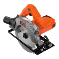
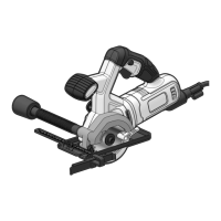
Do you have a question about the Black & Decker d984 and is the answer not in the manual?
Outlines what the reader will be able to do after reading this manual.
Explains the structure of the manual and the content of each chapter.
Lists other documents relevant to programming environments and system planning.
Provides instructions for inspecting shipments and handling returns.
Describes the Modicon 984 series controllers, their architecture, and capabilities.
Details the memory and I/O capacity for various 'E' controllers.
Explains the Optimize mode for ladder logic scanning on specific controllers.
Describes the compiler's process for creating efficient code in Optimize mode.
Explains the support for local I/O drops in Modicon 800 series housings.
Details support for remote I/O drops, including capacities and adapters.
Describes the two memory levels: executive firmware and user memory.
Lists executive IDs, CPU speeds, and DX functions for various PLC models.
Lists minimum requirements for supporting redundancy in 685/785 systems.
Describes Modicon 800 series primary and secondary enclosure options.
Details the standard 800 series I/O enclosures for remote I/O.
Explains the function of LEDs on the controller units.
Covers considerations for PLC systems, peripheral equipment, and site preparation.
Details clearance requirements for primary and secondary housings for cooling and access.
Discusses planning for power sources, cable routing, and dedicated lines.
Describes panel/bulkhead and rack mounting options for PLC system housings.
Details requirements for mounting H819 Module Housings in a standard EIA rack.
Provides guidance on grounding PLC housings using metal plates or ground straps.
Explains the built-in power supply operation for various controller models.
Specifies requirements for AC and DC power cables and their connections.
Covers communication options, switch configurations, and software settings.
Provides steps for installing housings using keyholes for panel or bulkhead mounting.
Details the procedure for attaching module housings to a rack using mounting flanges.
Explains how to route and connect field wiring to terminal blocks and wire connectors.
Guides on inserting I/O modules into designated slots and securing them.
Covers the installation and wiring of the P810 power supply module.
Details steps for verifying PLC and I/O configuration and operation.
Covers installation procedures for RI/O heads and receivers for specific PLC models.
Lists input power voltage, frequency, wattage, and fuse ratings.
Specifies current ratings for I/O service for different controller series.
Details requirements for AC isolation transformers and external 24Vdc power supplies.
Provides dimensions, weight, and slot requirements for controllers.
Lists static discharge, magnetic field, agency approval, and surge withstand ratings.
Details scan rate, throughput, and memory types.
Specifies operating and storage temperature, humidity, and altitude limits.
Lists part numbers for controllers, RI/O modules, power supplies, housings, and cables.
Lists machine stop bits and their corresponding error descriptions.
Provides wiring diagrams for various Modbus cable connections.
Offers a flowchart approach to troubleshooting PC system installation issues.
Explains MSTR block error codes, including major, minor, and sub-codes.
Provides Modicon telephone numbers and service categories for support.
| Brand | Black & Decker |
|---|---|
| Model | d984 |
| Category | Saw |
| Language | English |
