8
WARNING: Before assembly, make sure that the tool is
switched off and the battery has been removed.
ASSEMBLY TOOLS REQUIRED (NOT SUPPLIED):
- Phillips Screwdriver
WARNING: Remove the
battery before attempting to
attach any of the following
components.
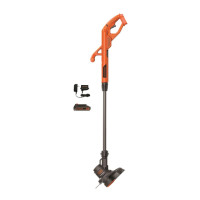
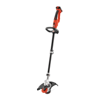
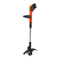
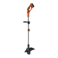
ATTACHING THE GUARD
(FIGURES D AND E)
WARNING: NEVER
OPERATE TOOL
WITHOUT GUARD FIRMLY
IN PLACE. The guard must
always be properly attached
on the tool to protect the user.
• Remove the screw from
the guard.
• Keeping the guard square
to the trimmer head slide it
into place until the retaining
tab clicks into place (Ensure
that the guide rails (D1) on
the guard (D2) are correctly
aligned with the guide rails
(D3) on the trimmer head
(D4) (figure D).
• Secure the guard with the
screw (E1) (figure E).
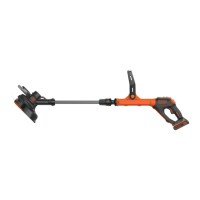
ATTACHING THE AUXILLARY HANDLE (FIGURES F AND G)
• Push the auxillary handle
(F1) onto the tube (F2).
Align the tab (F3) with the
slot in the tube.
• Lift the locking bar (G1)
into position.
• Close the auxillary handle
locking clamp (G2).
NOTE: If the auxillary
handle slackens over time it
can be re-tightened by
turning the locking bar (G1)
further into the handle
locking clamp (G2).
D
D2
D1
D3
D4
E
E1
F
F1
F2
F3
G
G1
G2
ASSEMBLY & ADJUSTMENT
 Loading...