conditionsthatmayaffecttheir
operation.Aguardorotherpartthatis
damagedshouldbeproperlyrepaired
orreplacedbyanauthorizedservice
centerunlessotherwiseindicated
elsewhereinthismanual.
• REPAIRSANDSERVICE.Repairs,
maintenanceandanyadjustments
notspecifiedinthismanualshould
beperformedbyBLACK+DECKER
authorizedservicecentersorother
qualifiedserviceorganizations,always
usingidenticalreplacementparts.
Z_WARNIN6: Some dust created by
this product contains chemicals known to
the State of California to cause cancer,
birth defects or other reproductive harm.
Some examples of these chemicals are:
• compounds in fertilizers
• compounds in insecticides, herbicides and
pesticides
• arsenic and chromium from chemically
treated lumber
To reduce your exposure to these chemi-
cals, wear approved safety equipment
such as dust masks that are specially
designed to filter out
microscopic particles.
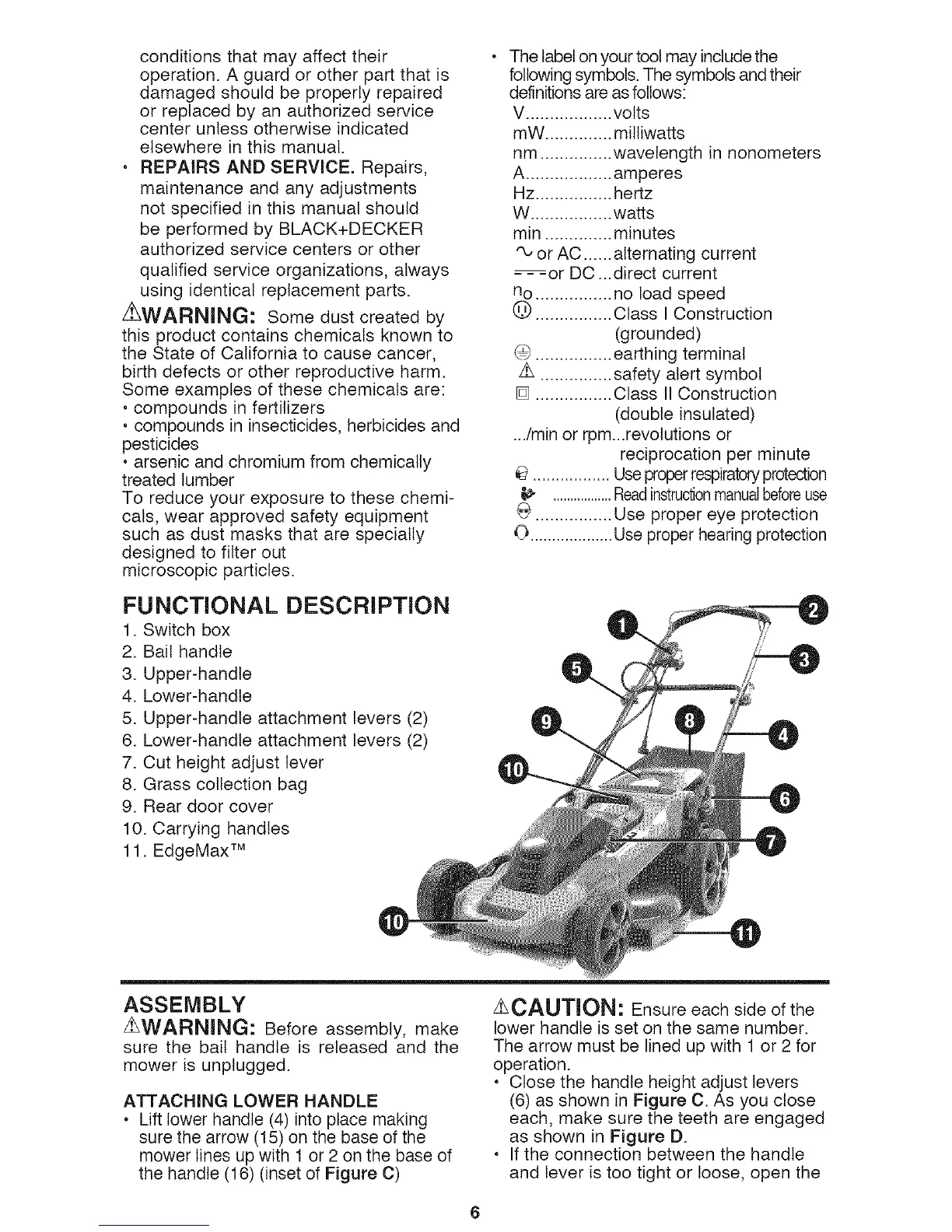
FUNCTIONAL DESCRIPTION
1. Switch box
2. Bail handle
3. Upper-handle
4. Lower-handle
5. Upper-handle attachment levers (2)
6. Lower-handle attachment levers (2)
7. Cut height adjust lever
8. Grass collection bag
9. Rear door cover
10. Carrying handles
11. EdgeMax TM
The labelon your tool may include the
following symbols.The symbols and their
definitionsare as follows:
V .................. volts
mW .............. milliwatts
nm ............... wavelength in nonometers
A .................. amperes
Hz................ hertz
W ................. watts
min .............. minutes
'_ or AC ...... alternating current
-- -or DC ...direct current
no ................ no load speed
@ ................ Class I Construction
(grounded)
G ................ earthing terminal
z_ ............... safety alert symbol
[] ................ Class II Construction
(double insulated)
.../min or rpm...revotutions or
reciprocation per minute
................. Useproperrespiratoryprotection
t_ .................Readinstructionmanualbeforeuse
G ................ Use proper eye protection
O ...................Use proper hearing protection
ASSEMBLY
Z_WARNING: Before assembly, make
sure the bail handle is released and the
mower is unplugged.
ATTACHING LOWER HANDLE
• Lift lower handle (4) into place making
sure the arrow (15) on the base of the
mower lines up with 1 or 2 on the base of
the handle (16) (inset of Figure C)
ACAUTION: Ensure each side of the
lower handle is set on the same number.
The arrow must be lined up with 1 or 2 for
operation.
• Close the handle height adjust levers
(6) as shown in Figure C. As you close
each, make sure the teeth are engaged
as shown in Figure D.
• If the connection between the handle
and lever is too tight or loose, open the

 Loading...