13
CHAPTER 4: Making Connections
4. Making Connections
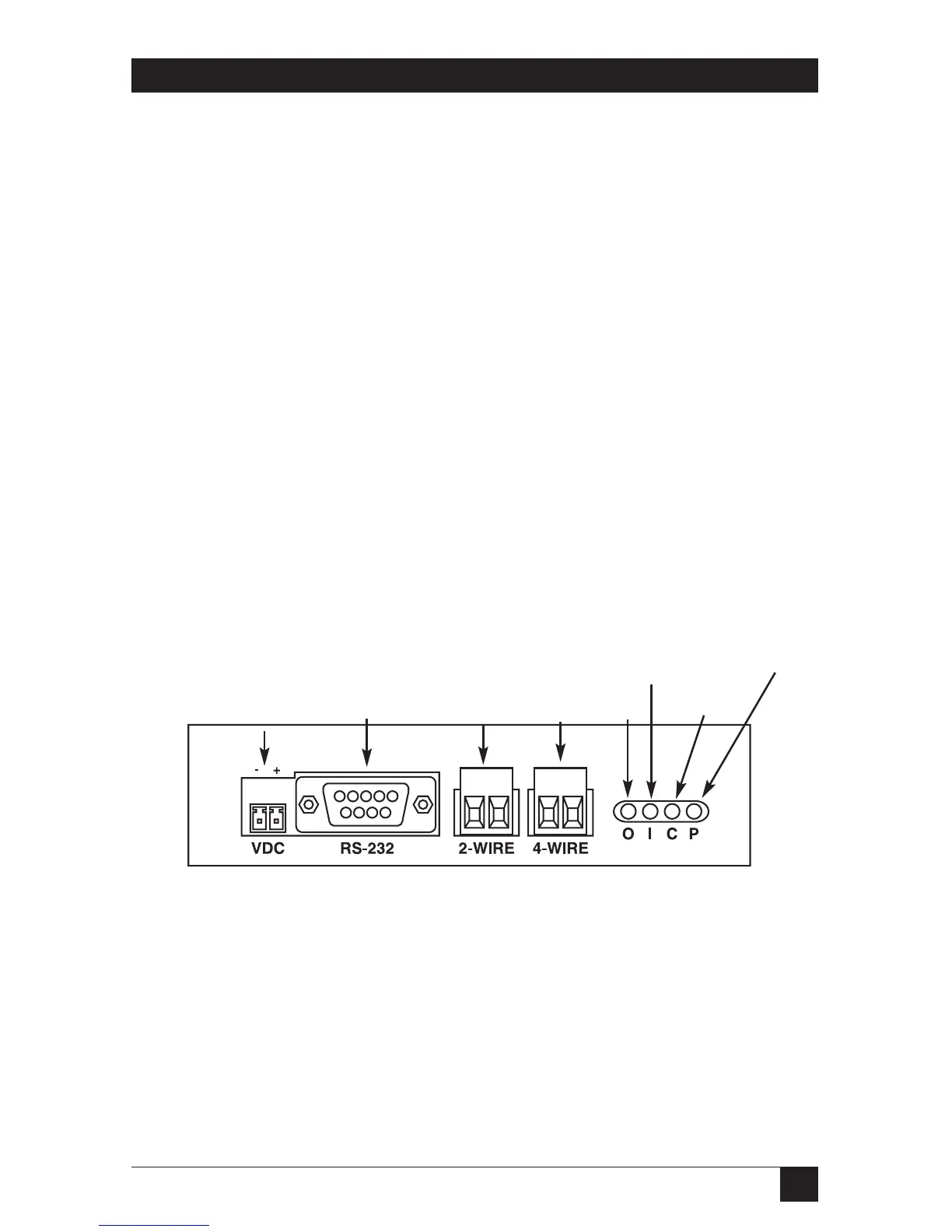
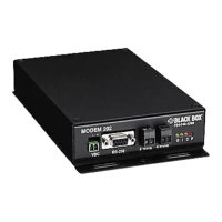
The Modem 202T has four connection points. (See Figure 4-1.) On the left is the
DC power connection. The standard modem has a two-position terminal block
connector for use with the supplied wallmount power supply. The DB9 connector
is the RS-232 interface. To the right of the DB9 connector are two connections for
the carrier wire pairs marked “2-Wire” and “4-Wire.” These are two-position
removable terminal block connectors. In 2-wire mode, the left connector acts as
both the transmitter and receiver connector. In 4-wire mode, the unit sends audio
tones out the 4-wire connector (transmit) and receives tones on the 2-wire
connector (receive). All connections to the phone lines are through 600-ohm
transformers.
NOTE
When using the Modem 202T in a 4-wire configuration, the transmitter of
the master “4-wire” must be connected to the “2-wire” of the remote(s)
and all remote transmitter “4-wires” are wired in parallel to the master’s
receiver connector “2-wire.”
4.1 Connections Diagram
Figure 4-1. Connections.
LED
S
• Power (P), red
• Carrier Detect (C), amber
• RS-232 In (I), yellow
• RS-232 Out (O), green
DC
Power In
Power
Connection
Serial
Interface
Carrier
Connections
LEDs
RS-232
2-wire
4-wire
Data
Out
Data
In
Carrier
Detect
Power


 To Next Page