14
MODEM 202T
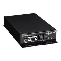
4.2 Power Connector
The two-position screw terminal connector is left pin negative (-) and right pin
positive (+). DC negative is not connected to the chassis.
4.3 RS-232 Serial Connector
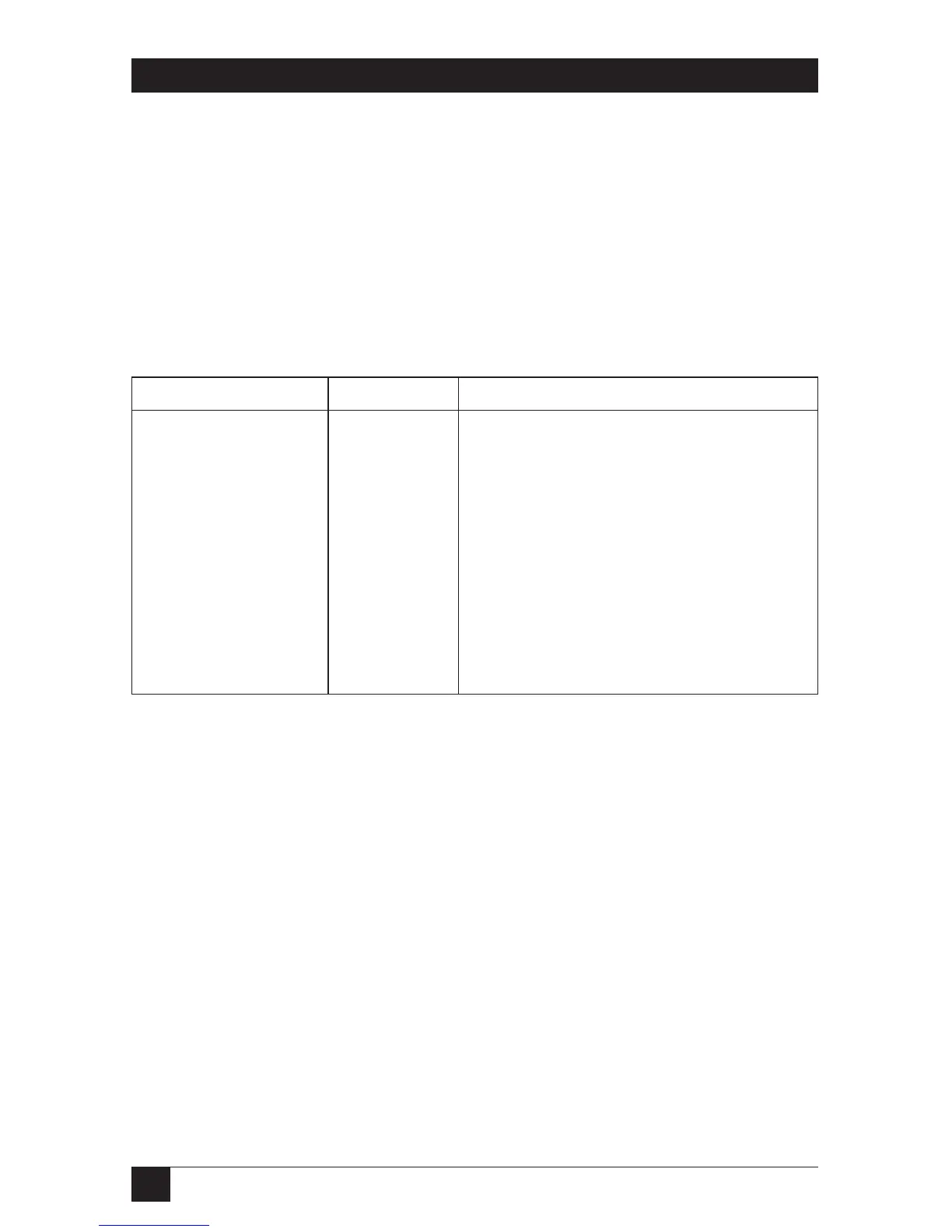
Table 4-1. RS-232 serial connector.
Pin Number Name Function
1 DCD* Received carrier detect out
2 TX RS-232 Data Out of Modem
3 RX RS-232 Data In to Modem
4 DTR Not connected in unit
5 Gnd Signal Ground
6 DSR* Data Set Ready (connected to CTS)
7 RTS* Ready to Send (transmit enable)
8 CTS Clear to Send [may be connected to
RTS or DCD] (connected to DSR)
9 RI Not connected in unit
*DCD via factory jumper to pin 1.


 To Next Page