184
MODEM 32144
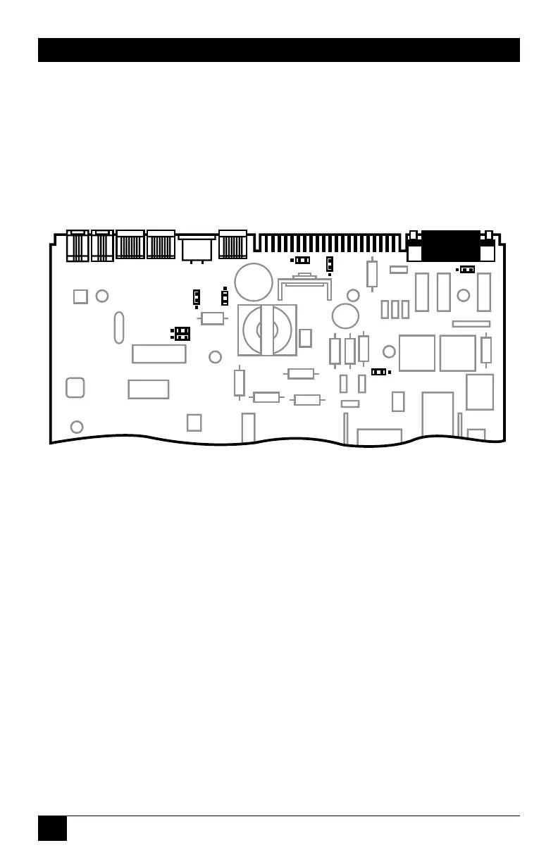
D.4 Jumper Locations
The jumper locations are shown
below for your information;
however, since the jumper settings
are pre-configured, you should not
have to change them.
Fig. D-2. Partial view of modem circuit board, showing jumper
locations.
For each jumper, pin 1 is
identified by a “1” on the modem
circuit board. (The JP2 pin 1 label
may be difficult to read; JP2 pin 1
is the pin closest to the edge
connector.)
 Loading...