9
CHAPTER 3: Connectors, Indicators, and Controls
3. Connectors, Indicators, and
Controls
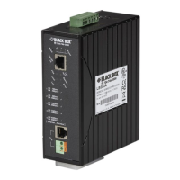
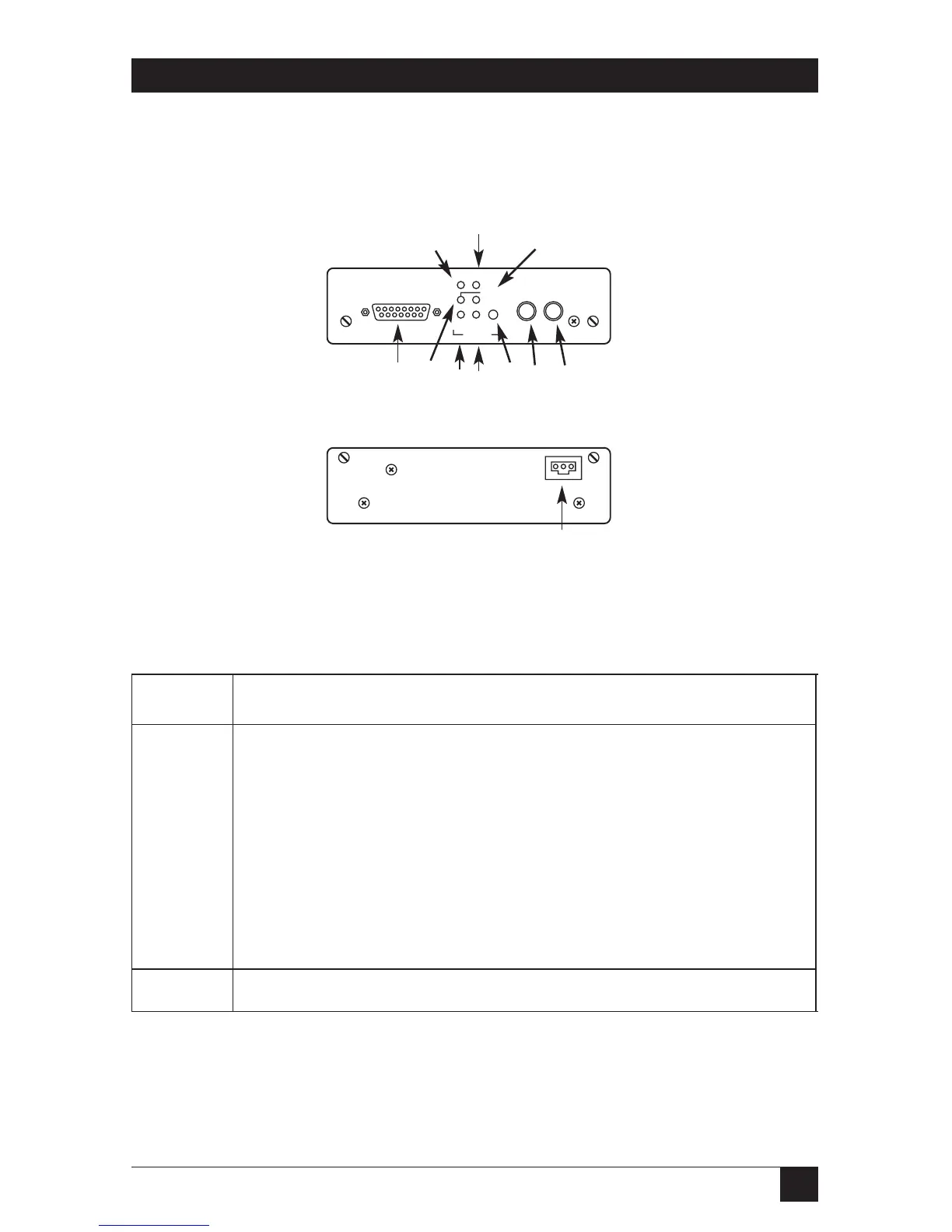
Figure 3-1. Front and Rear Panels.
Table 3-1. Connectors, Indicators, and Controls
No. Connector, Indicator, or Control
1 TX LED: Transmitting binary 0 via fiber optic
2 G.703 connector
3 FO/S LED: Power/FO Link/sync
4 LL LED: Unit in line loop mode*
5 DL LED: Unit in digital loop mode*
6 Loop mode button
7 ST connector for fiber optic receiver
8 ST connector for fiber optic transmitter
9 C LED: G.703 signal present
10 RX LED: Receiving binary 0 via fiber optic
A Power connector
*Both LEDs lit: Unit is in remote loop mode.