EasyManua.ls Logo

Black Horse Model CHIPMUNK BH44 User Manual

Black Horse Model CHIPMUNK BH44
29 pages
To Next Page IconTo Next Page
Page #1 background imageLoading...
Page #1 background image
Made in Vietnam.
SPECIFICATION
Wingspan : 1,630 mm 64.17in.
Length : 1,320 mm 51.97 in.
Weight : 3.3-3.5kg 7.26-7.70 lbs.
Servo : 07-08 servos.
Radio : 06channels.

Engine :
55- 61 cu.in-2 stroke.
91 cu.in-4 stroke.


Electric motor: Rim Fire.60


Battery: 5-6cells -Li-Poly-18.5-22.2V-5.000mAh.
ESC : 80A
INSTRUCTION MANUAL BOOK.
ITEM CODE: BH44.
Question and Answer IconNeed help?

Do you have a question about the Black Horse Model CHIPMUNK BH44 and is the answer not in the manual?

Black Horse Model CHIPMUNK BH44 Specifications

General IconGeneral
BrandBlack Horse Model
ModelCHIPMUNK BH44
CategoryToy
LanguageEnglish

Summary

Chipmunk Model Specifications

Aircraft Dimensions and Weight

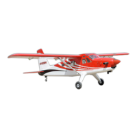
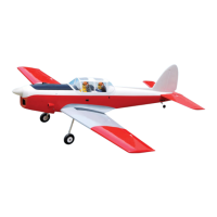
Details on the model's size (wingspan, length) and weight.

Power System Requirements

Specifications for engine, electric motor, battery, and ESC.

General Preparation and Warnings

Safety, Responsibility, and Club Advice

Critical safety warnings, assumption of risk, and flying club recommendations.

Tools, Supplies, and Assembly Tips

Lists necessary tools, supplies, suggestions, and notes for assembly.

Construction Guidelines and Safety

Model Cautions and Support Needs

Advisories about the model not being a toy and seeking expert support.

Film Covering Care and Construction Quality

Guidance on film covering maintenance and build accuracy.

Operational Safety Precautions

Crucial safety rules for operating the model safely.

Component Identification

Large and Small Parts Identification

Visual identification of major aircraft components and hardware.

Installing Aileron and Flap Servos

Servo Preparation and Tray Setup

Installing servo hardware and preparing the wing's servo tray.

Aileron Control Horn and Servo Mounting

Servo Mounting and Lead Routing

Drilling, routing servo leads, and installing servos in the wing.

Aileron Control Horn Attachment

Installing the control horn for the aileron.

Aileron Linkage Assembly

Pushrod Preparation and Bending

Preparing the pushrod wire by bending and cutting.

Linkage to Servo Connection

Connecting the pushrod to the servo arm and control horn.

Installing Flap Servos

Flap Servo Tray and Mounting

Installing the flap servo and tray into the wing.

Flap Control Horn and Linkage Installation

Flap Control Horn Attachment

Installing the control horn for the flap.

Flap Linkage Connection

Connecting the flap pushrod to the servo and horn.

Landing Gear Installation

Landing Gear Assembly and Attachment

Securing the oleo struts and wheels to the fuselage.

Landing Gear and Engine Mount

Securing Landing Gear Wheels

Finalizing the wheel attachment to the landing gear struts.

Engine Mount Installation

Attaching the engine mount to the fuselage.

Engine Installation

Throttle Pushrod Preparation

Drilling holes for throttle pushrod wire attachment.

Engine Mounting Procedure

Fitting the engine to the mount and securing it.

Fuel Tank Setup

Stopper Assembly and Tube Bending

Preparing the tank stopper and fuel lines.

Fuel Line Connections to Tank

Connecting fuel lines to the clunk, pickup, and vent tubes.

Fuel Tank Installation

Tank Stopper Fitment and Sealing

Testing and securing the stopper assembly in the fuel tank.

Fuel Line Routing and Tank Placement

Routing fuel lines and positioning the tank in the fuselage.

Throttle Pushrod Installation

Throttle Connector Attachment to Servo

Installing the metal connector onto the servo arm.

Securing the Throttle Linkage

Ensuring the throttle connector is securely fastened.

Cowling Installation

Cowling Positioning and Alignment

Sliding and aligning the fiberglass cowl over the engine.

Cowling Securing and Component Cutouts

Fastening the cowl and making necessary cutouts.

Spinner Installation

Spinner Backplate and Propeller Mounting

Attaching the spinner backplate and propeller.

Securing the Spinner Cone

Fastening the spinner cone in place.

Stabilizer and Elevator Servo Installation

Horizontal and Vertical Stabilizer Placement

Visual guide for stabilizer positioning.

Elevator Servo Mounting

Installing the elevator servo into its tray.

Stabilizer Gluing Procedure

Stabilizer Alignment and Epoxy Application

Gluing the horizontal and vertical stabilizers to the fuselage.

Elevator Control Horn and Pushrod

Elevator Control Horn Attachment

Installing the control horn for the elevator.

Elevator Pushrod Connection

Connecting the elevator pushrod to the servo and horn.

Rudder Servo Installation

Rudder Servo Mounting Procedure

Installing the rudder servo similar to the elevator servo.

Tail Wheel Bracket Mounting

Tail Wheel Bracket Placement and Marking

Positioning and marking the tail wheel bracket.

Tail Wheel Bracket Securing

Drilling pilot holes and screwing the bracket in place.

Rudder Control Horn Installation

Rudder Control Horn and Pushrod Assembly

Attaching the rudder control horn and pushrod.

Rudder Pushrod Preparation

Rudder Pushrod Wire Bending and Cutting

Preparing the rudder pushrod wire with bends and cuts.

Rudder Pushrod Installation

Rudder Pushrod Connection to Servo

Connecting the rudder pushrod to the servo arm.

Switch, Receiver, and Battery Installation

Switch Installation in Fuselage

Cutting and mounting the switch in the fuselage side.

Receiver and Battery Pack Securing

Securing the receiver and battery pack behind the fuel tank.

Wing Attachment and Assembly

Wing Dihedral Brace Fitment

Fitting the aluminium brace into the wing panels.

Wing Panel Attachment to Fuselage

Connecting the wing panels to the fuselage.

Airplane Balancing Procedure

Center of Gravity (CG) Identification

Identifying the critical balance point (CG) for the model.

Balancing Steps and Adjustments

Steps to check and adjust the model's balance for flight.

Control Throws and Pre-Flight Checks

Recommended Control Throw Settings

Specifications for control surface movement ranges.

Pre-Flight Inspection Checklist

Essential checks before the first flight.

Related product manuals