ENGLISH
BLACKSTONEPRODUCTS.COM/SUPPORT
OWNER’S MANUAL | USING YOUR BLACKSTONE
NATURAL GAS REQUIREMENTS
• The fixed fuel piping system must use a rigid pipe, semi-riged
tubing and/or a connector that complies with the Standard for
Connectors for Outdoor Gas Appliances and Manufactured Homes,
ANSI Z21.75 • CSA 6.27.
• This appliance has been designed and built to utilize natural gas
only. DO NOT attempt to operate this appliance using gases other
than natural gas at the indicated pressure.
• This appliance has been provided with a hose that must be used
for proper function. DO NOT replace the hose. If the hose becomes
worn or damaged, contact customer support for a replacement.
CONNECTING TO THE NATURAL GAS SUPPLY
STEP 01
Use an adjustable wrench to attach the natural gas hose
swivel fitting to the appliance.
STEP 02
If your natural gas supply line is not already set up with the
correct size Quick Connect/Disconnect fitting, the correct one is
included.
Note: Use thread sealant if attaching the provided Quick Connect/Disconnect
Note: Use thread sealant if attaching the provided Quick Connect/Disconnect
fitting. Thread sealant should be rated to 400° F (204°C) and be compatible with
fitting. Thread sealant should be rated to 400° F (204°C) and be compatible with
natural gas. (Permatex #59214 or Loctite 592)
natural gas. (Permatex #59214 or Loctite 592)
Note: To have the proper fitting added to your natural gas source, have this
Note: To have the proper fitting added to your natural gas source, have this
done by a licensed and insured professional.
done by a licensed and insured professional.
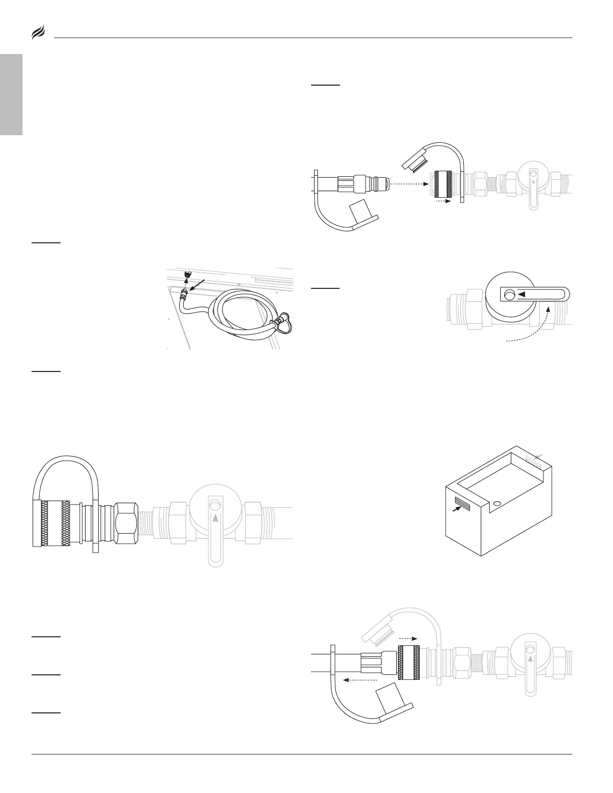
STEP 03
Connect your appliance to the natural gas supply from the
source by removing the dust covers and making sure both fittings
are free from any debris.
❶
Pull the locking collar back on the fitting
and
❷
push the male Quick Connect fitting all the way inside and
then release the locking collar.
Pull the hose and fitting in opposite directions to verify they are
connected.
STEP 04
Turn on the natural
gas supply.
Prior to turning on your appli-
ance, perform a leak test.
DISCONNECTING FROM THE NATURAL GAS SUPPLY
STEP 01
To disconnect your appliance for cleaning or storage, be sure
all of the control knobs are in the OFF position and the natural gas
supply at the Quick Connect valve is OFF.
STEP 02
❶
Pull the locking collar back and remove the natural
gas hose and release the locking collar.
❷
Pull apart the hose
and fitting.
STEP 03
Reinstall the dust covers on the supply line as well as the
natural gas hose on the appliance.
• Use a clean paintbrush to brush a mild soap and water solution
onto all the hose connections that you have completed.
• Bubbles will appear in the soapy water if any leaks are present.
• If you have any leaks, turn o your natural gas supply immediately
and fix any leaks before use.
Note: If you are unable to fix the leaks, call a qualified professional who is
Note: If you are unable to fix the leaks, call a qualified professional who is
licensed and insured.
•
DO NOT
route the gas supply hose
route the gas supply hose
directly underneath the appliance.
directly underneath the appliance.
DO NOT
route the hose underneath
route the hose underneath
or through permanent structures.
or through permanent structures.
•
The hose should be checked for
The hose should be checked for
cracks, cuts and wear each time
cracks, cuts and wear each time
you cook.
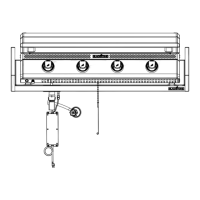
Swivel fitting
NG supply
(from house)
7"
water column
" Quick Connect fitting
" Quick Connect fitting
(included)
Thread reducer
(if required)
Shuto valve
OFF
Male Quick
Connect fitting
Locking collar
❶
OFF
OFF
❶
❷
OFF
ON
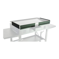
NATURAL GAS ENCLOSURE
CONSTRUCTION
A:
4x6 in (10x15 cm) vents at top, and
4x6 in (10x15 cm) vents at top, and
both sides of cabinet.
A
A
MODEL: 6301
 Loading...