101-C00 Page 5/20
BoWex® Couplings Mechanical Ratings “J” Style (NEMA & IEC)
Coupling
Type
Rated Torque
Cont. Peak
(Lb-in)
(N-m)
Input
Adapter
Sizes
Bore
Size
BoWex
®
J14
44.3
5
88.5
10
N56C 5/8”
BoWex
®
J24
106
12
212
24
N140TC 7/8”
BoWex
®
J28
398
45
1,195
135
N180TC
N180TC1
1-1/8”
BoWex® Couplings Mechanical Ratings “M” Style (NEMA & IEC)
Coupling
Type
Rated Torque
Cont. Peak
(Lb-in)
(N-m)
Input
Adapter
Sizes
Bore
Size
BoWex
®
M38
708
80
2,124
240
N180TC,
N210TC,
N250TC*
1-1/8”,
1-3/8”
BoWex
®
M42
885
100
2,655
300
N250TC* 1-5/8”
BoWex
®
M48
1,239
140
3,717
420
N280TC 1-7/8”
*GNX(H)2/2.5 N250TC Frame size uses BoWex
®
M38
*GNX(H)3/4 N250TC Frame size uses BoWex
®
M42
Rotex® Couplings
The cast iron jaw type couplings have an integral urethane
“spider” that provides smooth transmission of the motor
torque. A set screw on the coupling prohibits axial movement
along the motor shaft.
• Excellent shock and vibration dampening
• Excellent resistance to oils and most chemicals
• No metal-to-metal contact
• Operating Conditions: -22ºF - 195ºF (-30ºC - 90ºC)
• Higher temperature material (Hytrel) spider available up to
230ºF (110ºC)
• Low temperature materials available upon request
• Special bores available
Rotex® Couplings Mechanical Ratings “R” Style (NEMA & IEC)
Coupling
Type
Rated Torque
Cont. Peak
(Lb-in)
(N-m)
Input
Adapter
Sizes
Bore
Size
Rotex
®
R65
5,532
625
11,063
1,250
N320TC 2-3/8”
Rotex
®
R90
21,242
2400
42,484
4800
N360TC 1-5/8”
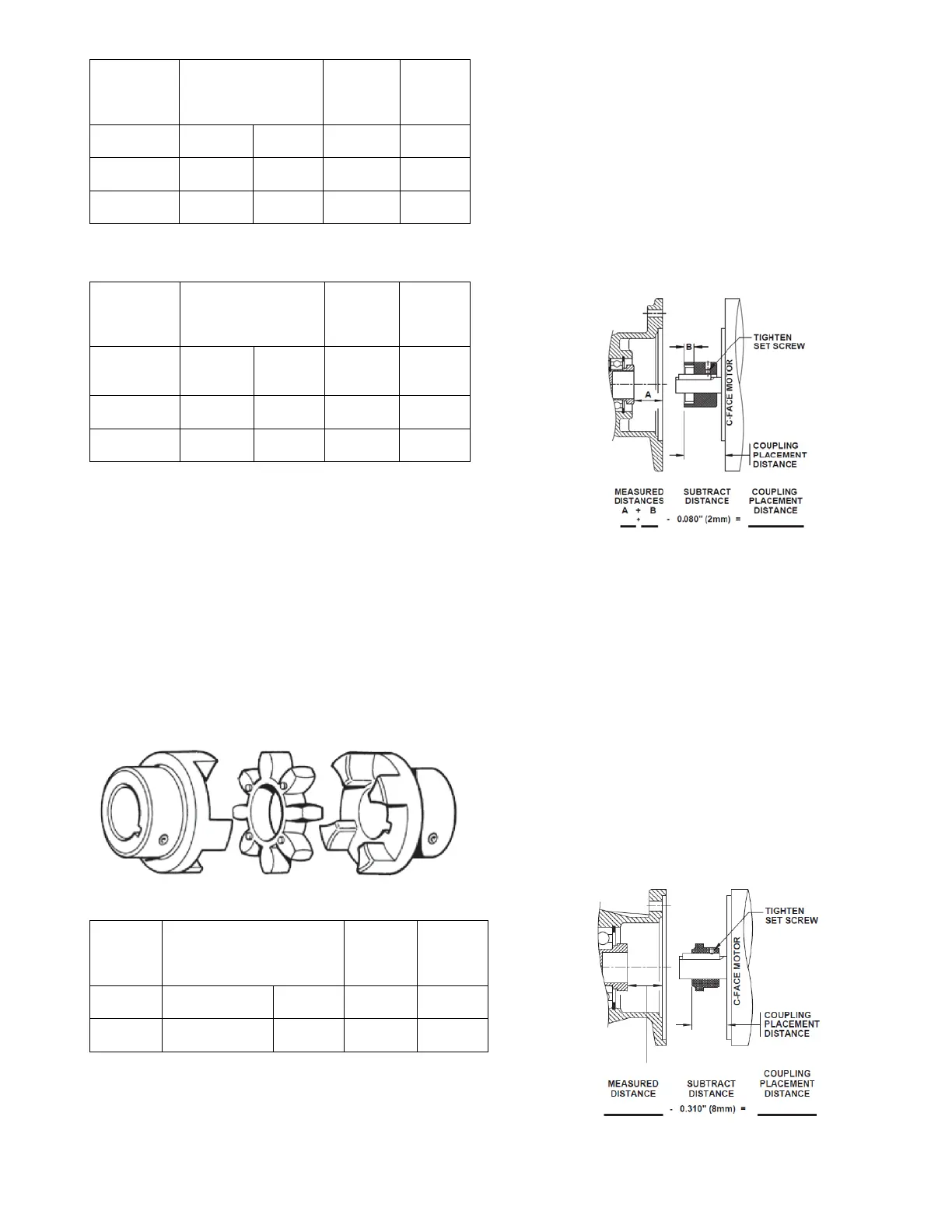
“J” Style Coupling NEMA C-face Motor Installation
1. Measure the distance from the face of the input adapter
to the face of the splined shaft and record that
measurement as A in the equation below.
2. Measure depth of coupling engagement zone and record
the measurement as “B” in the equation below.
3. Add “A” + “B” and subtract 0.08” (~2mm) from the
distance. This needs to be done so that the coupling will
not be preloaded after installation!
4. Use that measurement to locate the coupling from the
face of the motor onto the shaft.
5. Once in place, tighten the set screw to lock the coupling
in place. It is recommended that the key is staked or
bonded (Loctite) in place to prohibit the key from
vibrating out.
6. Mount the motor onto the input adapter with customer
supplied bolts. Make sure that the coupling from the
adapter and the motor engage securely. Use lock
washers or Loctite to prohibit bolts from becoming loose
from vibration.
“J” Style NEMA Motor Coupling Installation
“M” Style Coupling NEMA C-face Motor Installation
1. Measure the distance from the face of the input adapter
to the face of the splined shaft & record that
measurement.
2. Subtract 0.31” (~8mm) from the distance. This needs to
be done so that the coupling will not be preloaded after
installation!
3. Use that measurement to locate the coupling from the
face of the motor onto the shaft.
4. Once in place, tighten the set screw to lock the coupling
in place. It is recommended that the key is staked or
bonded (Loctite) in place to prohibit the key from
vibrating out.
5. Mount the motor onto the input adapter with customer
supplied bolts. Make sure that the coupling from the
adapter and the motor engage securely. Use lock
washers or Loctite to prohibit bolts from becoming loose
from vibration.
“M” Style NEMA Motor Coupling Installation


 To Next Page