VALVE REPLACEMENT
CB5A-021 page 18/24
MODELS LB361B, LB362C, LB601B, LB602C or
LB602B
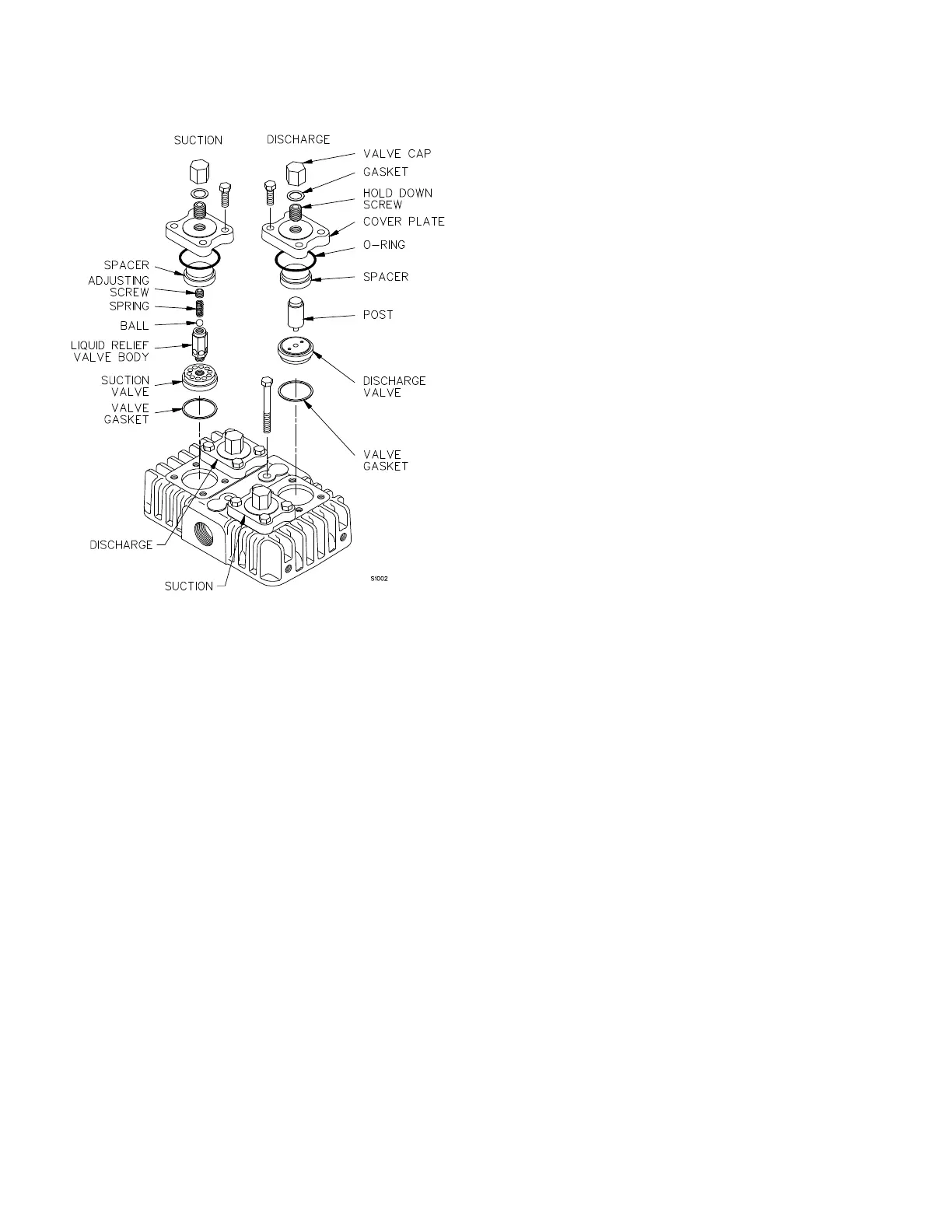
1. Remove the valve cap and gasket from the valve
being serviced.
2. Remove the valve hold down screw with an allen
wrench.
3. Remove the valve cover plate capscrews then lift off
the cover plate and O-ring.
4. Suction valves: remove the spacer, suction valve
assembly and valve gasket.
5. Discharge valves: remove the spacer, post,
discharge valve, and valve gasket.
6. Inspect the valve for wear or breakage. Repair or
replace as necessary.
7. To reinstall the suction valves:
a. Adjust the liquid relief valve adjusting screw
clockwise until the screw is flush with the top of
the liquid relief valve body, or no more than 1/16"
(1.6 mm) above the top of the liquid relief valve
body.
b. Ensure that the old gasket is removed, then
install a new valve gasket.
c. Install the valve assembly with the liquid relief
valve upward. Verify the correct valve
orientation and location.
d. Install the valve spacer.
e. Ensure the valve hold down screw is removed
from the cover plate, then place the cover plate
and new O-ring in position.
f. Install the valve cover plate capscrews and
tighten per Table 7 - "Bolt Torque."
g. Install and tighten the hold down screw per
Table 7 - "Bolt Torque."
h. Install the valve cap with a new gasket.
8. To reinstall the discharge valves:
a. Ensure that the old gasket is removed, then
install a new valve gasket.
b. Install the valve assembly with the plug
downward. Verify the correct valve orientation
and location.
c. Install the valve post, small end first.
d. Install the valve spacer.
e. Ensure the valve hold down screw is removed
from the cover plate, then place the cover plate
and new O-ring in position.
f. Install the valve cover plate capscrews and
tighten per Table 7 - "Bolt Torque."
g. Install and tighten the hold down screw per
Table 7 - "Bolt Torque."
h. Install the valve cap with a new gasket.
9. After replacing the valves, rotate the flywheel by
hand to check for interference between the pistons
and the valves.
10. After 60 minutes running time, remove the valve cap
and re-torque the hold down screw. Replace the
valve cap and gasket.
Figure 11 -
LB361, LB362, LB601 & LB602 Valves