960474
INSTRUCTIONS CB5A-021
Installation, Operation, and Maintenance Instructions
Section
Effective
Replaces
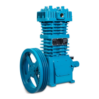
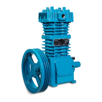
LB162B, LB362D, LB602C,
& Discontinued LB602B, LB362C
r130716
TABLE OF CONTENTS
Safety Data ............................................................. 1
General Information
Compressor Data ............................................... 2
Nameplate Data ................................................. 3
Maximizing Compressor Life .............................. 4
Installation
Location and Piping ............................................ 5
Mounting the Compressor Unit ........................... 5
Stationary Compressors ..................................... 5
Truck Mounted Compressors ............................. 5
Compressor Flywheel ........................................ 6
V-Belt Drive ........................................................ 6
PTO Drive .......................................................... 6
Liquefied Gas Transfer Piping Schematic .......... 7
Typical Transfer Compressor, Drawing .............. 7
Relief Valves ...................................................... 8
4-Way Valves ..................................................... 8
Liquid Traps ....................................................... 8
Temperature and Pressure Switches ........... 8 & 9
Pressure Gauges ............................................... 9
Operation
Pre-Startup Check List ......................................... 9
Start Up Procedure ............................................. 10
Maintenance
Service Schedule................................................ 11
Tool List .............................................................. 12
Bolt Torque Table ............................................... 12
Crankcase Lubrication ........................................ 13
Setting the Oil Pressure ...................................... 13
Compressor Disassembly ..................................... 14
Compressor Assembly .......................................... 15
Valve Replacement ................................................ 17
Seal (Packing) Replacement ................................. 19
S3R Seal Replacement .......................................... 20
Bearing Replacement ............................................ 21
Oil Pump Replacement .......................................... 22
Extended Storage .................................................. 22
Troubleshooting ..................................................... 23
This is a SAFETY ALERT SYMBOL.
When you see this symbol on the product, or in the
manual, look for one of the following signal words and
be alert to the potential for personal injury or property
damage.
Warns of hazards that WILL cause serious personal
injury, death or major property damage.
Warns of hazards that CAN cause serious personal
injury, death or major property damage.
Warns of hazards that CAN cause personal injury, or
property damage.
NOTICE
Indicates special instructions which are very important
and must be followed.
NOTICE
Blackmer compressors MUST only be installed in
systems which have been designed by qualified
engineering personnel. The system MUST conform to
all applicable local and national regulations and safety
standards.
These instructions are intended to assist in the
installation and operation of Blackmer compressors and
MUST be kept with the compressor.
Blackmer compressor service and maintenance shall
be performed by qualified technicians ONLY. Service
and maintenance shall conform to all applicable local
and national regulations and safety standards.
Thoroughly review this manual, all instructions and
hazard warnings, BEFORE performing any work on
the compressor.
Maintain ALL system and compressor operation and
hazard warning decals.
For handling liquefied gas, NFPA Pamphlet 58 should
be consulted.