8
ENGLISH
(Original instructions)
Voltage drops
Inrush currents cause short-time voltage drops. Under
unfavourable power supply conditions, other equipment may
be affected.
If the system impedance of the power supply is lower than
0.107Ω,disturbancesareunlikelytooccur.
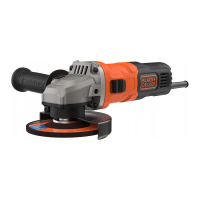
Features
This tool includes some or all of the following features.
1.On/offswitch
2. Spindle lock
3. Guard
4. Side handle
Assembly
Warning! Before assembly, make sure that the tool is
switched off and unplugged.
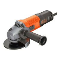
Fitting and removing the guard (g. A1, A2)
The tool is supplied with a guard intended for grinding
purposes only (type 27). If the unit is intended to perform
cuttingoffoperations,aguardspecicforthisoperation(type
41)mustbetted.AsuitableguardpartnumbersN642463
(for 115mm cutting wheel) can be obtained from
BLACK+DECKER service centres.
u Place the tool on a table, with the spindle (5) facing up.
u Align the lugs (7) with the notches (8).
u Press the guard down and rotate it clockwise to
the required position.
u Tighten the screw (6) to fix guard.
Removing
u Loosen the screw (6).
u Rotate the guard counter clockwise to align the lugs (7)
with the notches (8).
u Remove the guard from the tool.
Warning! Never use the tool without the guard.
Fitting the side handle
u Screw the side handle (4) into one of the mounting holes
in the tool.
Warning! Always use the side handle.
Fitting and removing grinding discs
(g. B - D)
Always use the correct type of disc for your application.
Always use discs with the correct diameter and bore size (see
technical data).
Fitting
u Fit the guard as described above.
u Placetheinnerange(10)ontothespindle(5)asshown
(g.B).
Makesurethattheangeiscorrectlylocatedon
theatsidesofthespindle.
u Placethedisc(11)ontothespindle(5)asshown(g.B).
If the disc has a raised centre (12), make sure that the
raisedcentrefacestheinnerange.
u Make sure that the disc locates correctly on the inner
ange.
u Placetheouterange(13)ontothespindle.Whentting
agrindingdisc,theraisedcentreontheouterangemust
facetowardsthedisc(Aing.C).Whenttingacutting
disc,theraisedcentreontheouterangemustfaceaway
fromthedisc(Bing.C).
u Keep the spindle lock (2) depressed and tighten the outer
angeusingthetwo-pinspanner(14)(g.D).
Removing
u Keep the spindle lock (2) depressed and loosen the outer
ange(13)usingthetwo-pinspanner(14)(g.D).
u Removetheouterange(13)andthedisc(11).
Surface grinding with grinding discs
u Allow the tool to reach full speed before touching the tool
to the work surface.
u Apply minimum pressure to the work surface, allowing the
tool to operate at high speed. Grinding rate is greatest
when the tool operates at high speed.
u Maintaina20˚to30˚anglebetweenthetoolandwork
surfaceasshowningureF.
u Continuously move the tool in a forward and back motion
to avoid creating gouges in the work surface.
u Remove the tool from work surface before turning tool off.
Allow the tool to stop rotating before laying it down.
Edge grinding with grinding discs
Wheels used for cutting and edge grinding may break or kick
back if they bend or twist while the tool is being used to do
cutoffworkordeepgrinding.Edgegrinding/cuttingwitha
Type 27 wheel must be limited to shallow cutting and notching,
less than 13 mm in depth when the wheel is new. Reduce the
depthofcutting/notchingequaltothereductionofthewheel
radius as it wears down. Refer to the 'Grinding and cutting
accessory chart' at the end of ths manual for more
information.Edgegrinding/cuttingwithaType41wheel
requires usage of a Type 41 guard.
u Allow the tool to reach full speed before touching the tool
to the work surface.
u Apply minimum pressure to the work surface, allowing the
tool to operate at high speed. Grinding rate is greatest
when the tool operates at high speed.
u Position yourself so that the openunderside of the wheel is
facing away from you.
u Once a cut is begun and a notch is established in the
workpiece, do not change the angle of the cut.