7
4b. Connect negative (–) black clamp to chassis or a solid, non-
moving, metal vehicle component or body part. Never clamp
directly to negative battery terminal or moving part. Refer to
the automobile owner’s manual.
5. Procedure for jump-starting POSITIVE GROUND SYSTEMS
Note: In the rare event that the vehicle to be started has a Positive Grounded
System (positive battery terminal is connected to chassis), replace steps
4a and 4b above with steps 5a and 5b, then proceed to step 6.
5a. Connect negative (–) black clamp to vehicle battery’s
negative terminal.
5b. Connect positive (+) red clamp to vehicle chassis or a solid,
non-moving, metal vehicle component or body part. Never
clamp directly to positive battery terminal or moving part.
Refer to the automobile owner’s manual.
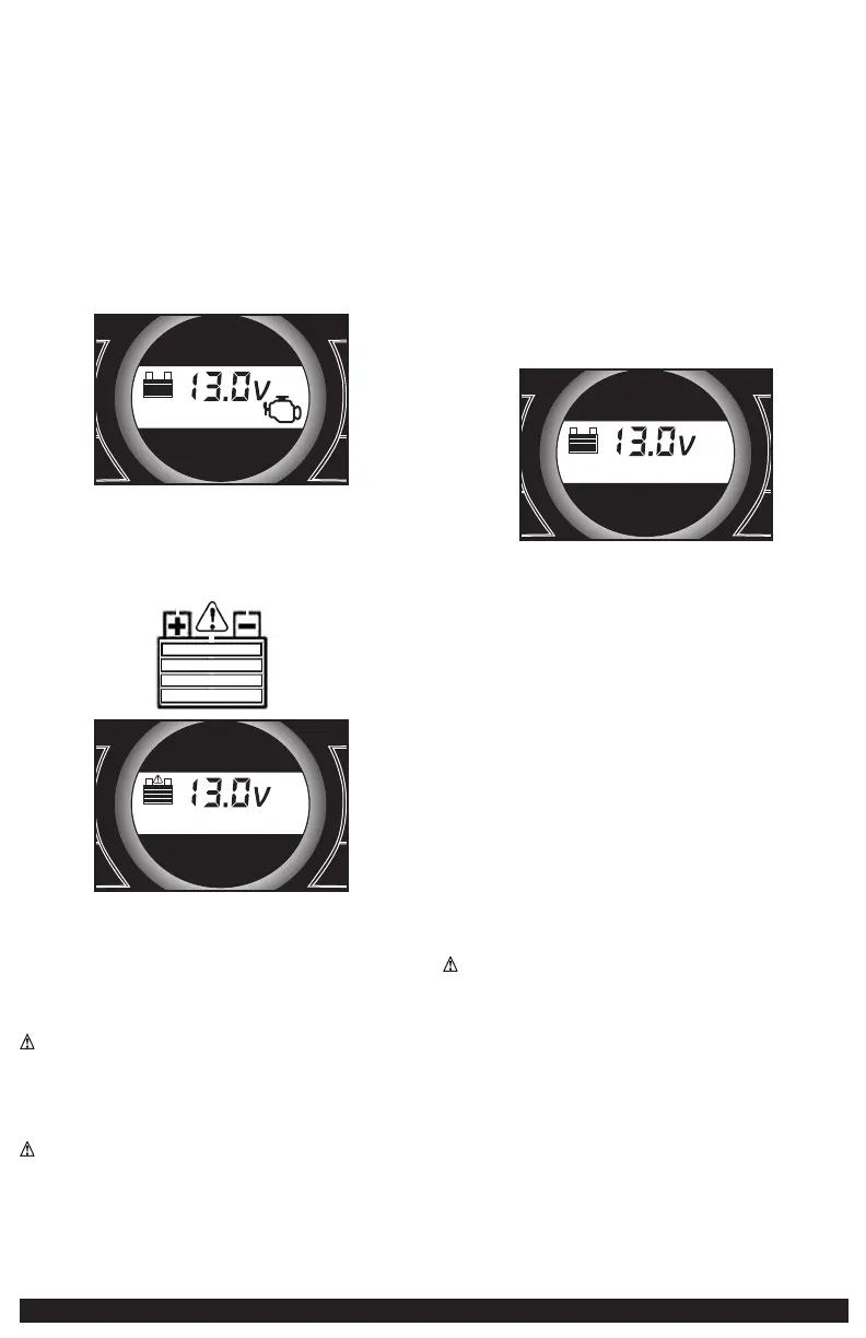
6. When the clamps are connected properly, the unit will automatically turn
on in jump-starter mode. The backlit LCD screen will display the following
to indicate the unit is ready to jump-start:
+
Area Light
Compressor
Battery
Status
USB
–
+
–
The jump starter icon will flash to indicate the clamps are properly
connected.
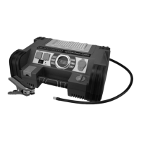
IMPORTANT: If the clamps are connected incorrectly with regard to
polarity, the reverse polarity connection alarm will sound continuously
and the backlit LCD screen will display the following (the “+” and”–”
signs and the alarm icon above the empty battery icon flash):
+
Area Light
Compressor
Battery
Status
USB
–
+
–
Disconnect clamps and reconnect to battery with correct polarity.
7. Turn the Jump-Starter Power Switch to ON.
8. Turn ON the ignition and crank the engine in 5-6 second bursts until
engine starts.
9. Turn the Jump-Starter Power Switch back to the OFF position.
10. Disconnect the negative (–) engine or chassis clamp first, then disconnect
the positive (+) battery clamp.
WARNING: TO REDUCE THE RISK OF INJURY OR PROPERTY DAMAGE:
• FOLLOW ALL SAFETY INSTRUCTIONS FOUND IN THE “Specific safety
instructions for jump starters” section of this instruction manual.
• Never touch red and black clamps together — this can cause dangerous
sparks, power arcing, and/or explosion.
• Always turn the unit off when not in use.
CAUTION: TO REDUCE THE RISK OF PROPERTY DAMAGE:
• Vehicles that have on-board computerized systems may be damaged if
vehicle battery is jump-started. Before jump-starting this type of vehicle,
read the vehicle manual to confirm that external-starting assistance is
advised.
• Excessive engine cranking can damage the vehicle‘s starter motor. If the
engine fails to start after the recommended number of attempts, discontinue
jump-start procedure and look for other problems that need to be corrected.
• If the connections to the battery’s positive and negative terminals are
incorrect, the LCD screen will display as shown in the second part of step 6
of the directions. Disconnect clamps and reconnect to battery with correct
polarity.
• If vehicle fails to start, turn off the ignition, turn off the Jump-Starter Power
Switch, disconnect the jump-start system’s leads and contact a qualified
technician to investigate why the engine did not start.
• Recharge this unit fully after each use.
LED AREA LIGHT
The built-in 3-LED area light is controlled by the area light power button on
the control panel (refer to the Features section to locate). Press the area light
power button once to turn the light on. Press the area light power button again
to turn the area light off.
IMPORTANT: When the area light power button is pressed to turn it on, a beep
will sound. The backlit LCD screen will turn on for 10 seconds (only) and will
then continuously display the battery status.
+
Area Light
Compressor
Battery
Status
USB
–
+
–
Periodically check the unit’s battery status on the LCD screen. Four solid bars
in the battery icon indicates a full battery. When the battery level is nearly
empty with only one solid bar, the unit MUST be recharged at this time or the
unit’s built-in low voltage protection will activate. The unit will sound a beep 5
times, then the area light will automatically turn off. The unit will then display
the battery status and voltage indicator for 10 seconds before automatic shut
down.
Make sure the area light and the unit are turned off when the unit is being
recharged or stored.
120 VOLT AC PORTABLE POWER SUPPLY
Rated Versus Actual Current Draw of Equipment
Most electrical tools, appliances, electronic devices and audio/visual
equipment have labels that indicate the power consumption in amps or watts.
Be sure that the power consumption of the item to be operated is below 500
watts. If the power consumption is rated in amps AC, simply multiply by the AC
volts (120) to determine the wattage.
Resistive loads are the easiest for this unit to run; however, it will not run
larger resistive loads (such as electric stoves and heaters), which require far
more wattage than the unit can deliver on a continuous basis. Inductive loads
(such as TVs and stereos) require more current to operate than do resistive
loads of the same wattage rating.
CAUTION: Rechargeable Devices
• Certain rechargeable devices are designed to be charged by plugging them
directly into an AC receptacle. These devices may damage the inverter or the
charging circuit.
• When using a rechargeable device, monitor its temperature for the initial ten
minutes of use to determine if it produces excessive heat.
• If excessive heat is produced, this indicates the device should not be used
with this inverter.
• This problem does not occur with most of the battery-operated equipment.
Most of these devices use a separate charger or transformer that is plugged
into an AC receptacle.
• The inverter is capable of running most chargers and transformers.
Note: Some laptop computers may not operate with this inverter.
 Loading...