13
EN
LED Indicator on FC Indicator Description
Red Solid
FC6250HX waiting for receiver
connection, system will not
initialize until connected
Yellow Flash Calibrating
Slow Green Flash Ready to Fly
Red and Yellow Flash
Failsafe Active
If the helicopter is experiencing drift issues after completing the trim fl ight procedure, perform the following calibration.
The calibration procedure may also be needed following crash repairs.
To perform the calibration procedure:
1. Ensure the surface used for calibration is level.
2. Power on the transmitter and helicopter, allowing
them to initialize.
3. Turn Throttle Hold ON.
4. Ensure the main motor is disconnected.
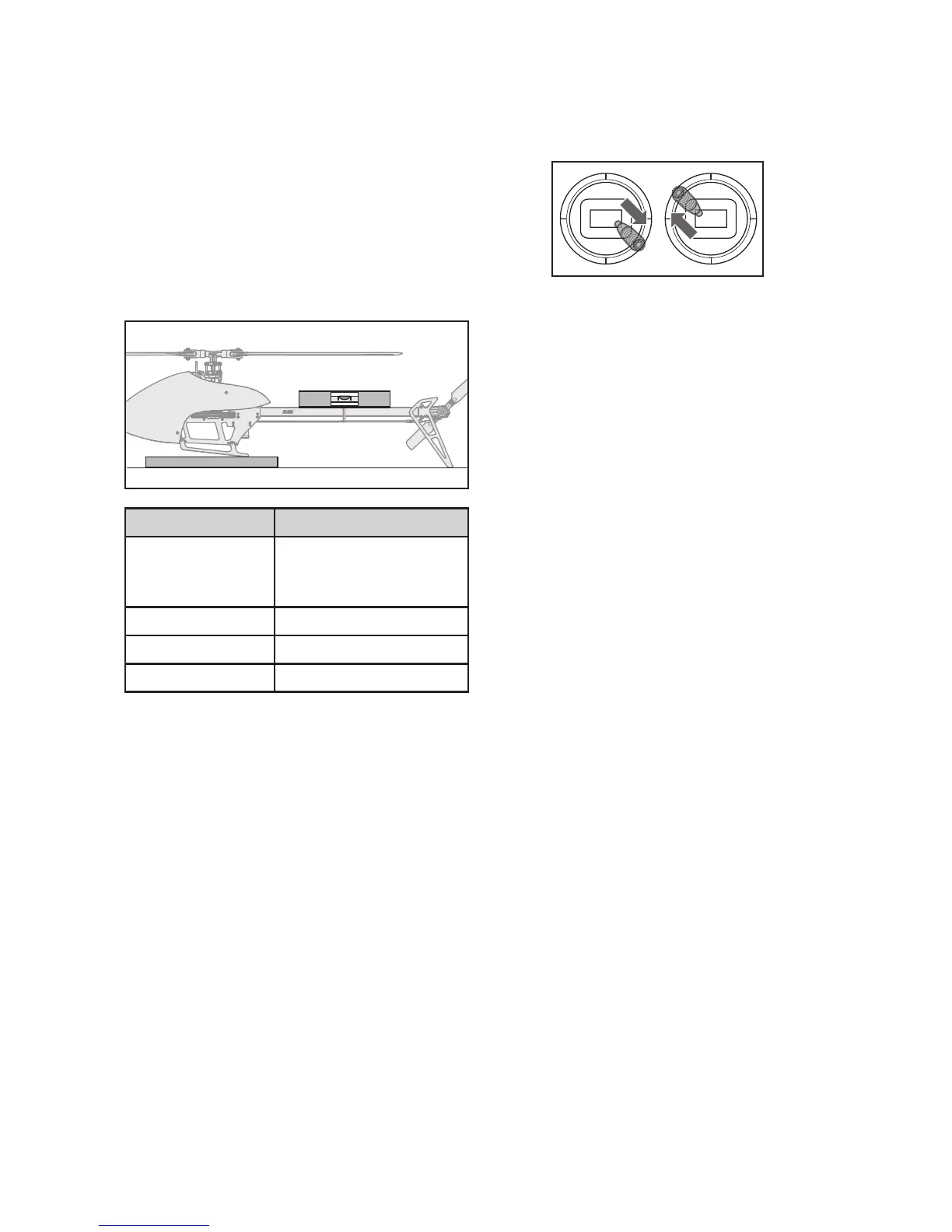
5. Using a bubble level as shown below, level the
helicopter by placing a shim under the landing skid.
6. Hold the left stick to the bottom right corner, and the
right stick to the upper left corner.
7. The LED on the Flight Controller will fl ash yellow
while caibrating
Do not move the helicopter until the calibration
is completed. If the LED displays a red LED an error
has occurred. Begin the calibration procedure again,
starting with step 1.
8. After the calibration is successfully completed, the
receiver LED will blink green.
Bubble level
Shim
Calibration Procedure